


Theory and Development of Frameless Stereotaxy
Jeffrey S. Henn, MD
G. Michael Lemole, Jr., MD
Mark Gerber, MD
Robert F. Spetzler, MD
Division of Neurological Surgery, Barrow Neurological Institute, St. Joseph’s Hospital and Medical Center, Phoenix, Arizona
Abstract
Frameless stereotaxy is a navigational technology that allows neurosurgeons to accurately determine their location and direction during surgery. Although frameless stereotaxy has only become practical in the last 20 years, various forms of intracranial localization and navigation have been used since at least the beginning of the 20th century. By considering the practical issues involved with frameless stereotaxy and the mathematical principles on which it is based, neurosurgeons can gain a better understanding of its potential applications and limitations.
Key Words: frameless stereotaxy, interactive image-guided surgery
Since the dawn of civilization man kind has endeavored to perfect the art of navigation. The ability to identify one’s location accurately remained a formidable challenge until just the last few centuries. Developing ingenious techniques, we have slowly mastered navigation over land, sea, and ultimately through space. It is perhaps natural that we now apply these techniques to the challenge of precisely navigating within the human body.
A Brief History of Nautical Navigation
Navigation is defined as the science of locating position or plotting one’s course. The earliest examples of navigation involved travel by land and depended on visual landmarks. As mankind took to the sea, sailors stayed close to the coast and continued to rely on visual landmarks. With the exception of the Vikings, few early sailors ventured beyond the sight of land.
To sail beyond the safety of a visible coast, sailors needed new skills to maintain a general sense of direction and location without obvious land-based visual references. Early oceanic sailors were both inventive and opportunistic. They learned to recognize clues for direction such as the position of stars, direction of flight of migratory birds, patterns of currents, and prevailing winds. To determine their location, early sailors learned to recognize obvious signs of nearby land including floating vegetation, birds, reflections on the sky, the taste and smell of water, and the depth and character of the bottom.[7] Even the Vikings, who more routinely traveled beyond the site of land, engaged in a form of short-distance island hopping. Areas with numerous islands allowed sailors to cautiously probe into the ocean without ever truly cutting the cord to nearby land.[7] Initially, these navigation skills were passed by word of mouth from father to son and master to apprentice.
Naturally, the next step was the creation of charts and maps. One of the earliest world maps was created by a Greek, Claudius Ptolemy. In about the year 150 A.D., he is credited with creating a text known as Geography. This revolutionary work recorded the location of several thousand places and also contained his famous map. Ptolemy’s contributions were “rediscovered” more than a millennium later, during the European Renaissance. At this time, the value of accurate charts and maps became increasingly evident. Probably the best known mapmakers were the Portuguese, who created accurate oceanographic charts that were extremely valuable and highly protected.
Another important advance in navigation was the invention of the magnetic compass. Although the inventors are debated and were perhaps either Chinese or Italian, the first written reference to a magnetic compass appeared in 1187 by an English monk.[14] The early compass was a magnetized needle that pointed north when floated in a bowl of water. By the 1400s, the compass was developed into a mechanical device with a pivot system. Using a compass, sailors could more precisely determine their direction of travel, but the issue of location remained a challenge.
Determining position on the sea comprised two separate challenges. The first was to determine latitude, or relative north-south position with reference to rotation of the earth. The second challenge was to determine longitude, or relative east-west location. The idea of representing location in terms of two separate axes dates to at least the Greeks. However, it was not until the 1600s that the field of “coordinate geometry” (now called analytic or Cartesian geometry) was developed by René Descartes. By introducing a coordinate axis on a two-dimensional plane, a location can be defined by an ordered number-pair, and each ordered number-pair identifies a particular location. Aside from advancing nautical navigation, Descartes’ contributions laid the foundation for the development of calculus by Newton.
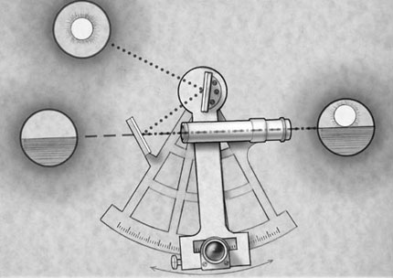
North-south position (latitude) was determined through accurate identification of the location of the sun and stars (Fig. 1). Using instruments such as the astrolabe, octant, quadrant, or cross-staff to determine the altitude of the stars, sailors in the 1400s and 1500s could determine latitude within 1 to 2º and hence their north-south position.[7] For many years, the combination of latitude and compass direction allowed sailors to navigate by traveling along known latitude parallels.[7] Relying on charts, sailors knew that if they traveled along a certain parallel (maintaining constant latitude) they would arrive at a planned location.
Determining longitude proved more vexing and is intertwined with a fascinating history. The earth’s east-west rotation implies that any celestial location is a function of the time at which an observation is made. However, highly accurate timepieces that could be taken on a nautical voyage did not exist. Several great scientists, including Galileo, dedicated tremendous time and effort to solving the problem of determining longitude.
Being able to determine longitude was critical because of the political situation at that time. Once only Spain and Portugal had controlled the seas, but Holland, England, France, and the North American and West Indian colonies of England were taking to the ocean.[7] Without knowing longitude, sailors were forced to follow a series of latitude parallels. As a result, they were unable to take the shortest route between two points. Furthermore, because sailors were forced to follow predictable routes, merchant vessels sailed under the constant threat of piracy.
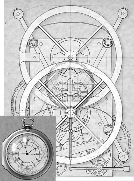
For these and other reasons, accurately determining longitude was considered extremely valuable and several large rewards were offered to anyone who could solve the problem. The largest and most famous reward (20,000 pounds, equivalent to $12 million dollars today) was offered in 1714 by the British government to anyone who could solve the problem.[7] For years, the prize went unclaimed, until 1759 when a watchmaker named John Harrison developed an extremely accurate marine chronometer that allowed sailors to keep accurate time for weeks or even months (Fig. 2). A comparison of time from a known reference location to local time (determined by astronomical observation) could be converted into longitude based on the rotation of the earth (one revolution in a 24-hour day). Thus, the problem of longitude was overcome.
For centuries sailors navigated based on these principles, and cartographers created highly accurate maps of the ocean and land. Of course, these techniques have since been replaced by modern methods of satellite triangulation. Contemporary sailors can now find their location to within a few yards with relative ease. Furthermore, using an inexpensive handheld global positioning system, one can determine their exact location anywhere on earth. Technology has reduced one of the greatest challenges faced by mankind to the mere press of a button!
The development of intracranial navigation is intimately tied to the history of nautical navigation. Almost every mathematical development and technological advance used for frameless stereotaxy have their origin in overcoming the challenges of nautical navigation. There are also some interesting parallels between the development of nautical navigation and surgical intracranial navigation.
Just as early sailors were limited to navigating by the site of land, so too early neurosurgeons relied solely on the use of external and internal landmarks when performing cranial surgery. In fact, the word “landmark” reveals its origins in nautical navigation. Just as charts and maps were invaluable for navigation, modern imaging studies such as computed tomography (CT) and magnetic resonance (MR) imaging provide detailed maps of a patient’s anatomy by which a surgeon can navigate within the skull. Finally, just as advances in nautical navigation were intimately tied to technological breakthroughs, frameless stereotaxy would be infeasible without the development of the digital computer, accurate position sensors, and modern imaging studies. To some extent, the contemporary neurosurgeon is a descendant of the early sailor who first set off over the ocean, relying on both skills and technology to navigate safely.
A Brief History of Intracranial Navigation
The earliest cranial procedures were performed in the Neolithic period of the Stone Age in the form of trephinations.[16] In widely separated geographical locations, archeologists have discovered human skulls with craniectomy defects. Many of these skulls show evidence of healing along the edges, suggesting that the patients survived the operation. Unfortunately, the rationale for these procedures and possible methods of localization are unknown as there are no written records from this era.[16]
The Edwin Smith Papyrus from the 17th century B.C. contains the earliest written descriptions of the anatomy of the skull and brain.[16] This document contains descriptions of brain injuries related to functional changes in other parts of the body. It does not include trephinations, and the treatment of neurologic injury involved only supportive measures. Hippocrates’ writings contain the first description of trephinations.[16] They also elaborated on manifestations of neurologic injury and documented common patterns of neurologic injury and effect.
Modern neurosurgery did not become feasible until the introduction of anesthesia and asepsis in the mid19th century.[16] However, except for lesions involving the skull, no method yet existed for localizing intracranial pathology. This development awaited the contributions of Broca and others who demonstrated that body functions are focally represented within the brain.[16] With the introduction of the concept of cerebral localization, surgeons could for the first time consider surgical treatment of brain lesions based on clinical examination. The need for techniques to accurately locate surgical lesions predicted by clinical localization soon followed. To a great extent, clinical neurological localization and the resulting development of early techniques of intracranial navigation represent the dawn of modern neurosurgery. Unfortunately, clinical localization has limits. In this era, large craniotomies were routine and negative surgical explorations occasionally resulted from “false-localizing” clinical signs.
The introduction of radiographic imaging revolutionized lesion localization in medicine. In fact, the first “image-guided surgery” occurred only eight days after Roentgen’s discovery of X-rays when a buried needle was removed from a woman’s hand with the help of a radiograph.[10] However, early application of plain radiographs to intracranial pathology was limited. Except for foreign bodies and calcified masses, most brain lesions are not visible on plain radiographs. With the development of pneumoventriculography in 1918 by Dandy, mass lesions could be more readily localized.[16] The addition of carotid arteriography in 1927 by the Portuguese neurologist Antonio Egas Moniz allowed vascular lesions to be visualized and further contributed to localizing mass lesions.[16] These techniques proved invaluable to the development of neurosurgery, but the science of neurosurgical navigation remained limited.
Although the first “stereotactic instrument” was developed in 1889 by a Russian surgeon, D. N. Zernov, the details of its use are limited.[1,17] His “encephalometer” was a frame that was apparently fixated to a person’s skull with navigation based on a polar coordinate system referenced to a patient’s external anatomy. Apparently, this device was used to treat a number of patients with lesions of the brain.[1]
The first atlas-based system, although not for human use, was described in 1908 by Horsley and Clark.[1,5,10] The frame-based system was used to allow the precise placement of electrodes into a monkey’s brain and was referenced to external landmarks. Using this technique, atlas-based anatomy was applied to localization in an individual animal. Horsley and Clark coined the term “stereotaxic,” which derives from the Greek words stereos (three-dimensional) and taxis (system).[5,10] In contemporary usage, the term stereotaxic has largely been replaced by stereotactic, with its origins in the Latin tactus (to touch).[4]
The first application of “modern” frame-based stereotaxy to humans was in 1947 when Spiegel and Wycis published their pioneering work, Stereotaxic apparatus for operation on the human brain.[1,13] They also published a human atlas based on intracranial landmarks identified by pneumo encephalography. Their work resulted in stereotactically guided treatment for movement disorders, chronic pain, epilepsy, and psychiatric diseases. Over the next decades, several more frame systems were developed. Target points were typically determined using standard human atlases, by localizing a target on two orthogonal images, or by a combination of these two.
In the early 1970s, the development of CT led to a revolution in neurological diagnosis, three- dimensional localization, and stereotaxy. Stereotactic targets could now be based entirely on the anatomy of an individual patient, eliminating the need to generalize from an atlas. Because of its inherent three- dimensional coordinate system, CT represented an ideal tool for frame-based stereotaxy. Navigation based on CT data involved identifying the three- dimensional location of a target within the stereotactic frame. Because CT data are collected in a series of axial slices, the displayed information is inherently two-dimensional (represented relative to the x and y axes). The z axis is not intrinsic to the slice but represents the position of a given axial slice relative to the others. In early stereotactic systems, the z-axis value was determined based on the distances moved by the CT table between slices. However, this technique suffered from several errors including head movement between slice acquisition and imprecision of table movements.[10] The goal was to develop a method to encode the z axis value within each axial slice. The problem was elegantly solved by the “N-bar” method.[2,4,10] Using this technique, three radio-opaque bars are placed in an “N” configuration next to the patient’s head. As the axial slice is obtained, each bar is seen in cross section. The relative distances between the center bar and the side bars mathematically determine the z-axis value. In practical application, three sets of N-shaped bars are used so that relative head-tilt can also be accounted for mathematically. Similar techniques for framed stereotaxy have been designed for MR imaging.
The major advantage of framed stereotactic systems is that the rigid metal frame serves to maintain a fixed three- dimensional coordinate system. Unfortunately, the frame is also the system’s greatest limitation. The bulky assembly limits head positioning and physically interferes with performing a craniotomy. The arc assembly for aiming is non-intuitive, non-interactive, and limited to a single trajectory at a time.[10] Consequently, framed systems tend to be reserved for procedures such as needle biopsy or placement of depth electrodes.
The natural goal was to develop a system for image-based, intracranial navigation independent of an external frame. Beginning in the 1980s, investigators pursued methods for applying the three- dimensional imaging data of CT and MR imaging to intracranial navigation. Several systems have been developed, each based on a combination of three fundamental concepts: (1) correlating physical space and image space, (2) using a “pointing device” for interactive localization, and (3) obtaining image-guided feedback through a computer-based interface.[10]
General Techniques of Frameless Stereotaxy
Mathematical Principles
A Cartesian coordinate system is a three- dimensional grid with a center point (origin) that can be used to map locations in space. A point is located within the coordinate system by specifying its value along each of three axes (traditionally x, y, and z). Each unique x, y, z coordinate represents a specific location in three- dimensional space. The position of an entire object in a coordinate system can be determined by specifying the location of every point in the object in relation to the origin of the coordinate system. Different coordinate systems may be used to define different spaces, such as image space and physical space.
Basic Concepts of Registration
Frameless stereotaxy is based on the creation of a mathematical relationship between radiographic images and physical space. This process, known as registration, involves the precise mapping of every location in an image to the corresponding physical anatomy of the patient (i.e., mapping image space onto physical space).[10,12] After registration, the image becomes a literal “map” for neurosurgical navigation. Because the relationship between image space and physical space is defined mathematically, both image and anatomy must be represented in terms of three-dimensional coordinate systems. Once accomplished, the process of registration is reduced to determining the relationship between the two coordinate systems and mapping one onto the other.
Image-Space Coordinates
The development of CT and MR im aging, which provided high- resolution, spatially accurate three- dimensional information in a defined coordinate system, was prerequisite for frameless stereotaxy. During image acquisition, each physical location is represented in terms of its three- dimensional position and an intensity value. In the case of image space, the required three-dimensional coordinate system is inherent to the image itself.
Although imaging systems vary in terms of the origin and orientation of their Cartesian axes, for the purpose of this discussion the following convention is employed for intracranial imaging. The x axis defines left-right and increases when moving from left to right. The y axis defines anterior-posterior (from the back of the patient to the front) and increases when moving forward. The z axis defines inferior-superior (running in a cranio-sacral orientation) and increases when moving cranially. A standard axial view would therefore represent a specific z plane and would incorporate an x and y axis. Each point in the image is identified by a unique x, y, and z coordinate and a corresponding intensity value.
Physical-Space Coordinates
The process of defining a three- dimensional coordinate system for the patient’s anatomy is more complex. Because physical space does not provide its own inherent coordinate system, one must be applied and maintained throughout the procedure. The process of defining a stable coordinate system in physical space is accomplished with the use of an interactive localizing device (ILD).[10] This “pointing” device should uniquely identify points in physical space, be accurate and consistent, and be easy to use in the surgical setting. The ILD has its own inherent three- dimensional coordinate system, which is effectively applied to the patient’s anatomy.
Once applied, the coordinate system must remain constant throughout registration and the subsequent surgery. Either a fixed relationship must be maintained between the patient and the ILD, or any change in the relationship must be quantitated accurately. The need for a stable coordinate system precludes unexpected movement of the patient during surgery. Consequently, in the case of cranial surgery, the patient’s head must be rigidly fixated, for example, in a Mayfield head-holder.
After the patient has been rigidly fixated, the ILD and the patient are “joined.” The inherent coordinate system of the ILD becomes the coordinate system for the physical space of the patient. Several types of ILDs exist and may be classified as either linked (a direct physical connection between the patient and the ILD) or nonlinked (no direct physical connection but some other definable relationship).[10]
Linked Interactive Localizing Devices
In the case of linked systems, a rigid physical connection exists between the ILD and the patient (i.e., the patient’s head is rigidly fixated to operating table; the ILD is rigidly fixated to the same part of the operating table). Because the relationship between the ILD and the patient is rigid, the coordinate system remains stable unless the physical connection between patient and ILD is changed.
Intraoperative movement of the operating table is allowed as long as the patient and the ILD move as a single unit. Movement of the patient is not precluded, but a constant relationship between the patient and the predefined coordinate system is required.
Examples of linked ILDs include active robotic arms and passive articulated arms. In 1985 Kwoh et al. described a robotic arm used for this application—the PUMA industrial robot (Westinghouse Electric, Pittsburgh, PA) for CT-directed stereotactic surgery.[6]
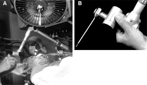
This system was limited because the bulky arm was restrictive in the surgical setting. Passive articulated arm ILDs rely on proprioceptive joint angle sensors to determine the position of a probe tip attached to the end of the arm. In 1987 Watanabe et al. first described the application of a passive localizing arm to neurosurgical navigation.[15] Their articulated arm includes six joints, which allowed the arm to be moved in and out of the surgical field with relative ease, making it practical for use. The way in which the arm was able to “sample” surgical space also proved to be intuitive to surgeons.[10] The ISG Viewing Wand System (ISG Technologies, Mississauga, Ontario, Canada) is another passive articulated arm that has been used extensively in neurosurgery.[8] This arm is composed of two segments and six joints, which give it a 60-cm reach and six degrees of freedom (Fig. 3). The joint sensors are electro potentiometers (Faro Technologies, Lake Mary, FL) that relay analog signals to a computer. The signals are converted to digital and combined to determine the location of the probe tip in three- dimensional space.
Linked ILDs have been used extensively, are relatively uncomplicated, and have an excellent track record. Still, they have inherent limitations. The rigid connection between the articulated arm and the patient requires that the device occupy part of the critical working space around the surgical field. In addition, when working under the operating microscope, the physical structure of an articulated arm makes it difficult to maneuver into the operative field. Nevertheless, we have used the ISG system extensively at our institution and reported our experience with 1112 procedures.[8] In cases when the ISG system was used, it was determined to have assisted in planning the craniotomy in more than 80% of patients with arteriovenous malformations, metastases, and cavernous malformations. The system was also thought to be very helpful for localizing parenchymal lesions such as gliomas and cavernous malformations.
Nonlinked Interactive Localizing Devices
Nonlinked ILDs establish a stable three- dimensional coordinate system in physical space without being physically connected to the patient. These systems require a precise method of identifying locations in physical space without a direct mechanical connection. Examples include sonic triangulation; infrared light-emitting diode (LED) triangulation; and more novel techniques such as machine vision-passive video, magnetic field deflection, and inertial guidance systems.[10] Even nonlinked systems, however, use a linked referencing attachment, which allows a constant update of relative head positioning; this system is known as dynamic referencing.
The earliest nonlinked ILDs were based on the technique of sonic triangulation using spark-gap emitters.[11] Arrays of sound detectors were used to triangulate the precise location of the sound emitters and to create a three-dimensional coordinate system. This technology has several potential limitations: the speed of sound is highly dependent on temperature, echoes can lead to interference, and the path between emitter and detector needs to be clear of physical barriers.[10]
As a result, sonic triangulation has largely been replaced by infrared LED triangulation systems. Based on similar mathematical concepts, these systems employ linear charge-coupled device three-camera arrays for the purpose of triangulating LED locations. A variation employed by some systems is to emit infrared light from the camera unit and triangulate the location of reflecting elements. Although line-of-site is still required between the LED and camera, the concerns about temperature and echo are removed.
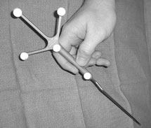
Although fundamentally more complicated than linked systems, the technology of nonlinked ILDs has several intrinsic advantages. Because emitters are being localized, they may be applied to any rigid localizing tool. As a result, the tools have the advantage of being “free-hand,” with no restraints of physical connection (Fig. 4). In addition, almost any rigid tool can be converted to a localizing device. In fact, the newest systems allow a localizing array to be applied to a surgical instrument in the operating room, thereby “converting” it to a localizing device. This feature represents one of the ultimate promises of nonlinked ILDs: to incorporate the localizing function into standard neurosurgical instruments.
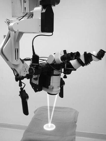
Perhaps the most elegant manner in which the localizing function is incorporated into a neurosurgical instrument is in the case of the operating microscope. Several systems have been developed in which the operating microscope itself can function as a localizing device. One example is the Leica Viewscope (Leica, Inc., Deerfield, IL), in which the pointing function is performed with two low-energy lasers designed to converge to a single point at the focal length of the microscope (Fig. 5). Based on this length and the location of the microscope, the precise point of focus can be determined in terms of its x, y, z coordinates. After mapping this point to image space, the corresponding location on the imaging studies can be visualized. Alternative systems do not use the laser; instead, they use the center of the field of focus to perform the same function. In either case, these systems have the advantage of continuous update without the need for a separate localizing instrument. After the operating microscope has been registered and brought into position, the surgeon can view the image information at any time and gain feedback about the anatomy being visualized. Although most systems require the surgeon to look away temporarily from the operating field to the computer display, some newer systems incorporate heads-up display of the frameless stereotactic data.
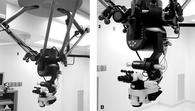
Another example of a frameless stereotactic microscope is the Elekta SurgiScope (Elekta, Stockholm, Sweden; Fig. 6). This robotically controlled operating microscope demonstrates even more integration of frameless ste reotaxy with the microscope. The SurgiScope also uses a convergent laser system for frameless stereotactic feedback. In addition, the SurgiScope allows preoperative planning based on the imaging data, which can be used to direct the scope to move to planned trajectories. In this case, the frameless stereotactic system serves not only to provide feedback but provides the surgeon the opportunity to identify the planned approach to the lesion preoperatively.
Techniques of Registration
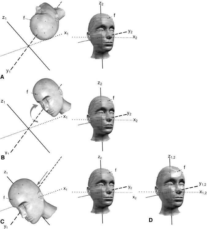
Having effectively defined a Cartesian coordinate system for image space and physical space, the next step is to determine the mathematical relationship that maps one to the other (Fig. 7). This process is accomplished in two conceptual steps. First, a rotation is applied to one of the coordinate systems around its origin to place the axes of the two systems into the same orientation. Second, a three- dimensional linear translation allows the object in one system to be aligned with the object in the other system. This combination of rotation and translation becomes a mathematical transformation and provides a map to relate each point in one coordinate system to the corresponding point in the other.
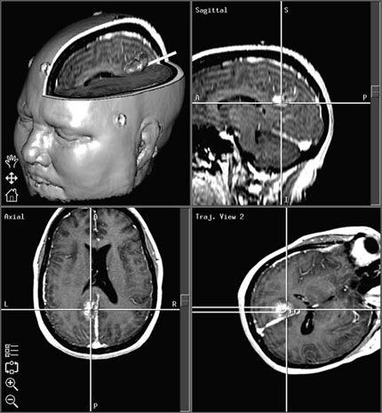
After this transformation has been defined, any point identified in physical space with the ILD results in the display of the corresponding point in the imaging study (Fig. 8). Thus, the surgeon can readily determine location and trajectory throughout the surgical procedure—the result is navigation.
A computer workstation, which is the core of the system, performs the mathematical calculations and interactive image display. In order for the computer to calculate the mathematical transformation and to create registration, corresponding points must be identified in both image space and physical space.
Paired-Point Registration
The most common method of registration is the paired-point method. A series of points (at least four, but typically more) is identified in both physical space and image space (Fig. 3A).[12] A cursor is used to identify each point in the displayed image, and the ILD is then used to identify the corresponding physical point. These points, which may be natural landmarks or artificial fiducials, need to be specific and readily identifiable. Although the use of natural anatomic landmarks allows registration to be completely retrospective, the technique is subject to significant inaccuracies and is rarely used.[9] Instead, artificial fiducials are typically applied before imaging. At our institution we favor donut-shaped self-adhesive markers, which are visualized on both CT and MR imaging. The markers must not be moved between the time of imaging and registration. Consequently, we routinely place markers and obtain scans immediately before surgery. Typically, a temporary ink mark is made on the skin at the center of each fiducial to avoid problems associated with unexpected movement. Although rarely necessary, an alternative is to use markers that are rigidly fixated to the skull.
After a series of corresponding points have been identified, the computer can determine the transformation between image and physical space. A “best-fit” is mathematically determined to correlate the configuration of points in image space with the corresponding points in physical space. The relative accuracy of this “best-fit” algorithm is provided as feedback during registration.
Surface Registration
Surface-based registration systems match numerous points extracted from natural contours. Unlike point-based registration, in which corresponding points are matched, surface-based registration attempts to align the contour of a physical surface (such as the scalp) with a corresponding image surface. For example, software algorithms can be used to analyze the image data and to define the surface of the scalp mathematically based on the marked contrast of the air-skin interface. After numerous points on the surface of the patient’s scalp are identified with a localizing device, the computer is able to create a best-fit match. Typically, the more points that are identified in physical space, the better defined is the surface and the better the fit. Because surface registration is mathematically complex, many systems first require paired-point registration and then use surface registration to improve accuracy.
Registration Error
The ideal registration would involve a perfect mapping between image space and physical space, and would be maintained throughout the duration of the procedure. However, practical application of frameless stereotaxy always involves sources of error that must be considered and minimized. In some cases, the computer system is able to provide feedback regarding registration error.
One potential source of error is intrinsic to the images themselves.[3] Every imaging study has an intrinsic spatial resolution, usually limited by the slice thickness. In the case of CT, this resolution is conceptually straightforward. In the case of MR imaging, the physics are more complicated. Certain tissues respond differently to the magnetic field and may lead to spatial shift (known as chemical shift).[3] In addition, metal artifact results in a region of surrounding spatial distortion. Various techniques are used to minimize spatial distortion.
Paired-point registration involves the use of a few discrete points to establish the mathematical transformation between image and physical space. Another source of error is inaccurate identification of these points. It is essential that corresponding points be precisely identified on the images and on the patient. In most cases, identification of external natural landmarks fails to provide the necessary accuracy and increases error results. As an alternative, external fiducials can be used. The fiducials should be firmly affixed and the center should be marked in case of inadvertent movement after the imaging study. The image study should ideally be performed immediately prior to surgery to minimize the chance of fiducial movement.
Thoughtful placement of fiducials helps minimize error. Depending on the planned approach, fiducials should be placed to allow easier access for registration. In addition, error is theoretically minimized at the epicenter of the registered points so fiducials should be placed on the scalp so they “surround” the lesion.[12] Posterior scalp fiducials require separate consideration. During image acquisition the patient’s posterior scalp is displaced by the weight of their head. As a result, the location of posterior scalp fiducials may be different after surgical positioning and may result in increased error.
During the process of registration, a “best-fit” algorithm is determined. The computer is able to provide feedback regarding the accuracy of registration. Specifically, the mean fiducial error (MFE) is a number that reflects how accurately the points identified in physical space can be mapped onto image space.[12] A low MFE implies that the computer is able to find a very close match between the points identified in each space. As a corollary, the computer can also provide feedback about the relative contribution of each point to the MFE. If one point is associated with a high error, it is usually safe to assume that there was error in localizing the point. By removing this point and recalculating registration, it is possible to remove a source of significant error. A low MFE is a usually a good indicator that registration is accurate. However, a low MFE only implies that the configuration of the points in image space matches well with the configuration of points in physical space. In unusual cases, a low MFE may be misleading. For example, consider the case of intraoperative registration of the spine. If several points are identified on a vertebra and used for registration, a low MFE implies that the configuration of the points matches well with those on the image. If registration, however, is off by one vertebral level, the similar shape of the adjacent vertebrae would lead to a similar configuration of points. The result would be a low MFE but a very inaccurate registration.
Even when registration is accurate, other sources of error must be considered. An example is error that results from shifting of the brain and surrounding soft tissue. Sometimes, opening the dura can cause the brain to shift away from or to swell into the opening. This scenario is particularly true when significant atrophy is present or when osmotic diuretics are used. Removing tumors or other mass lesions also leads to a progressive loss of correlation between image and physical space. These shifts can be dramatic and can eclipse an otherwise accurate registration. Techniques for limiting error associated with shift are discussed in the next section.
Techniques of Registration Update
Frameless stereotaxy permits neurosurgical navigation based on a continuous interactive update of the surgeon’s position relative to radiographic images. Even with a perfect registration, however, the act of performing surgery changes anatomical relationships. Common examples include shift of the brain after the skull has been opened or a mass lesion is removed.[8] Because registration is performed based on preoperative images, changes in the patient’s anatomy relative to these preoperative scans can significantly alter the accuracy of frameless stereotaxic systems. Neurosurgeons have become adept at conceptualizing these changes and, to some degree, accounting for them. An ideal system, however, should provide registration from physical space to images that are continuously updated to reflect the changing anatomy.
The most definitive solution to this problem is the use of intraoperative MR imaging. Using a combination of intraoperative MR imaging and frameless stereotaxy, the neurosurgeon can periodically update the references images and reregister physical space to the updated image space. In this manner, the neurosurgeon’s navigational maps are updated to reflect the changing anatomy. However, intraoperative MR imaging is not yet universally available. It is also expensive and can limit the surgeons’ operating space.
Intraoperative ultrasonography can also provide feedback to the neurosurgeon about shift and, occasionally, tumor resection. In these systems, a planar ultrasound image is compared side-by-side with the equivalent planar MR image from the preoperative radiographic study. In this manner, the neurosurgeon can visualize and take into account changes such as the degree of shift.
Potential Benefits of Frameless Stereotactic Navigation
The main advantage of frameless stereotaxy is that it provides real-time updated information to the surgeon about location and trajectory. By providing this type of feedback, frameless stereotaxy offers many potential benefits. Depending on the details of a case, the frameless stereotactic feedback can be helpful in localizing lesions, increasing the chances of complete lesion resection, and helping to identify normal structures surrounding a lesion. Typically, the result is faster, more complete, and often safer neurosurgical procedures.
Before performing every craniotomy, the surgeon must decide on the size and location of the skin incision and cranial window. Frameless stereotaxy, with its millimeter accuracy and line-of-site trajectories, allows the skin incision and craniotomy to be placed precisely. This precision is invaluable when planning tumor resections or craniotomies near a dural venous sinus. In addition, frameless stereotaxy allows the incision and craniotomy to be just large enough to accomplish the surgical goal safely. The result is a smaller skin incision, improved craniotomy placement, and less chance of inadvertent venous sinus injury. Frameless stereotaxy is also of tremendous benefit for defining intraoperative anatomy and for lesion localization.
Resection of intraparenchymal tumors is also improved with frameless stereotaxy. Corticotomies may be placed precisely and directed along the optimal trajectory. In tumors with poorly defined margins, the constant feedback on location can be invaluable to maximizing tumor resection while minimizing brain injury. The extent of resection can also be verified by sweeping the probe around the resection cavity.[10]
Conclusion
While neurosurgery is a relatively young surgical specialty, the art of navigation has existed in some form since the dawn of mankind. By “standing on the shoulders of giants,” contemporary neurosurgeons can take advantage of the countless breakthroughs, victories, and failures that are the history of navigation. Although frameless stereotaxy will never be a replacement for surgical skill, it is a powerful weapon in the armamentarium of contemporary neurosurgeons.
Acknowledgments
The authors thank Bradford S. Burling and Medtronic Surgical Navigation Technologies for their valuable technical support.
References
- Alexander E, III, Nashold BS, Jr.: A history of neurosurgical navigation, in Alexander E, III, Maciunas RJ (eds): Advanced Neurosurgical Navigation. New York: Thieme, 1999, pp 3-14
- Brown R: A stereotactic head frame for use with CT body scanners. Invest Radiol 14:300-304, 1979
- Bucholz R, Levy AL, Marzouk S: Computed tomography and magnetic resonance imaging as neurosurgical imaging data sets, in Alexander E, III, Maciunas RJ (eds): Advanced Neurosurgical Navigation. New York: Thieme, 1999, pp 35-48
- Heilbrun MP: Frameless stereotactic localization and guidance, in Youmans JR (ed): Neurological Surgery: A Comprehensive Reference Guide to the Diagnosis and Management of Neurosurgical Problems. Philadelphia: W.B. Saunders, 1999, pp 786-794
- Horsley V, Clarke RH: The structure of the cerebellus examined by a new method. Brain 31:45-124, 1908
- Kwoh YS, Hou J, Jonckheere EA, et al: A robot with improved absolute positioning accuracy for CT guided stereotactic brain surgery. IEEE Trans Biomed Eng 35:153-160, 1988
- Landes DS: Finding the point at sea, in Andrewes WJH (ed): The Quest for Longitude. Cambridge, MA: Collection of Historical Scientific Instruments, 1996, pp 20-30
- Lawton MT, Spetzler RF: Clinical experience with a frameless stereotactic arm in intracranial neurosurgery, in Alexander E, III, Maciunas RJ (eds): Advanced Neurosurgical Navigation. New York: Thieme, 1999, pp 321-332
- Maciunas RJ: (Frameless stereotactic) interactive image-guided neurosurgery, in Rengachary SS, Wilkins RH (eds): Neurosurgery. New York: McGraw-Hill, 1996, pp 4107-4118
- Maciunas RJ: Overview of interactive image-guided neurosurgery: Principles, applications, and new techniques, in Alexander E, III, Maciunas RJ (eds): Advanced Neurosurgical Navigaton. New York: Thieme, 1999, pp 15-32
- Roberts DW, Strohbehn JW, Hatch JF, et al: A frameless stereotaxic integration of computerized tomographic imaging and the operating microscope. J Neurosurg 65:545-549, 1986
- Sofamor Danek: StealthStation Treatment Guidance Platform. Understanding StealthStation System Registration. Memphis: Sofamor Danek, 1999
- Spiegel EA, Wycix HT, Marks M, et al: Stereotactic apparatus for operations on the human brain. Science 106:349-350, 1947
- Stimson A: The longitude problem: The navigator’s story, in Andrewes WJH (ed): The Quest for Longitude. Cambridge, MA: Collection of Historical Scientific Instruments, 1996, pp 72-84
- Watanabe E, Watanabe T, Manaka S, et al: Three-dimensional digitizer (neuronavigator): New equipment for computed tomography-guided stereotaxic surgery. Surg Neurol 27:543-547, 1987
- Wilkins RH: Historical aspects, in Sabiston I, David C, Jr. (eds): Textbook of Surgery: The Biological Basis of Modern Surgical Practice. Philadelphia: W.B. Saunders, 1991, pp 1235-1236
- Zernov DN: Encephalometer. A device for determination of the location of brain parts of living humans. Proceedings of the Society of Physico medicine, Moscow 2:70-86, 1889