
Internal Fixation and Fusion of the Lumbar Spine Using Threaded Interbody Cages
Author
Curtis A. Dickman, MD
Division of Neurological Surgery, Barrow Neurological Institute, Mercy Healthcare Arizona, Phoenix, Arizona
Abstract
Recently, threaded interbody fusion cages have become available for clinical use to treat degenerative disc disease and instability in the lumbar spine. These hollow, fenestrated, fixation devices are inserted into the lumbar disc spaces and are filled with bone grafts. They act to distract a collapsed disc space and to open stenotic neural foramina, to stabilize the spinal motion segment, and to promote interbody bone fusion. These devices have several clinical and biomechanical advantages compared to pedicle screws and other fixation techniques for the lumbar spine. The threaded cages may be inserted by using anterior lumbar interbody fusion or posterior lumbar interbody fusion techniques, by open surgical approaches, or by endoscopic approaches.
Key Words : degenerative disc, interbody fusion, lumbar spine, spinal instability, spondylolisthesis, threaded interbody fusion cages
Threaded interbody fusion cages are a viable alternative for treating degenerative disc disease and grade I or II spondylolisthesis of the lumbar spine. These devices have several clinical and biomechanical advantages compared to other types of posterior hardware and posterolateral fusions. The cages can distract the disc spaces to normal heights, apply tension to the annulus and spinal ligaments, widen the neural foramen, place the implants under compression, and eliminate segmental motion to stabilize the spine. This article reviews the clinical application of these devices including related pathophysiology, indications, patient selection, biomechanics, insertion techniques, and clinical outcomes.
History of Lumbar Interbody Fusion Devices
Interbody fusion has been applied to the cervical, thoracic, and lumbar spinal segments using a variety of techniques. In the 1950s, the neurosurgeon Ralph Cloward pioneered the original techniques for posterior lumbar interbody fusion (PLIF) across an intervertebral disc space and had excellent clinical outcomes with the technique.6 Since then, anterior interbody fusion has become a common procedure after an anterior discectomy has been performed in the cervical spine.
PLIF, however, never achieved widespread clinical popularity for several reasons. First, application of the interbody bone grafts was technically difficult. Dural retraction also was required. Finally, the lumbar spine could not be fixated rigidly while the bone graft was incorporated and consolidated.2,7,23 During the last two decades, posterior lumbar spinal fixation devices (e.g., pedicle screws, hook rods) have become popular for the fixation of unstable spinal segments. Consequently, posterolateral bone grafting techniques (i.e., facet fusion and intertransverse process fusion) have become the most popular methods to achieve arthrodesis across the vertebrae because the posterolateral bone surfaces are immediately available for access, and no additional exposure or dural retraction is required.
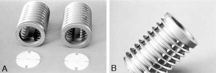
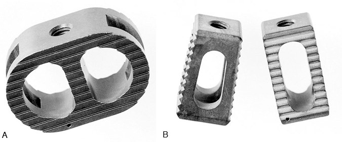
Figure 2. The Ray Threaded Fusion Cage™ (Surgical Dynamics Corp., Norwalk, CT) has broad V-shaped threads and longitudinal fenestrations along the length of the cage at 90° intervals. It is made of a moderately flexible titanium alloy. (A) The radiolucent caps are used to cover the ends of the cages to prevent displacement of graft material. (B) A lateral view demonstrates the fenestration pattern and thread profile of the cages. With permission from Surgical Dynamics.
Interbody fusion cages, recently developed spinal implant devices, are fostering a re-examination of the treatment paradigms for degenerative disc disease and degenerative lumbar spinal instability. Current fixation devices are based upon a hollow, stainless steel, perforated cylinder called the “Bagby Basket.”1 This device was used to fuse the cervical spine of thoroughbred horses with “Wobbler syndrome,” an ataxic myelopathy caused by cervical spinal instability. The fusion cages were filled with autograft bone and inserted into the disc spaces after the vertebrae were distracted. This device has been very successful in treating horses.
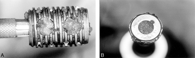
In the 1980s, the design of the Bagby Basket was modified for use in the lumbar spine in humans. Dr. Stephen Kuslich collaborated with Dr. George Bagby to produce a hollow, fenestrated, threaded titanium cylinder called the BAK™ (Spine-Tech, Inc., Minneapolis, MN) device.17,27 Like the Bagby Basket, the BAK device is filled with autograft and screwed into threaded channels cut into the distracted intervertebral disc space (Fig. 1). Between 1992 and 1995, the use of the device was investigated in 947 patients. In September 1996, it was approved by the Food and Drug Administration (FDA) for both open anterior lumbar interbody fusion (ALIF) and PLIF.27 In July 1997, the BAK device was approved by the FDA for laparoscopic ALIF.
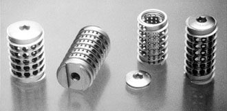
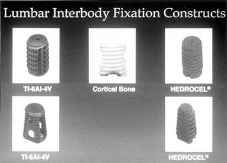
Other threaded lumbar interbody fusion devices are available clinically or are currently being studied under FDA investigational device exemption (IDE) study protocols. Dr. Charles Ray developed the Ray Threaded Fusion Cage™ (Surgical Dynamics Corp., Norwalk, CT), which also has been approved by the FDA for open PLIF (Fig. 2).19,20 Further modifications to interbody fusion cages include the shape of the implants (i.e., trapezoidal shape to recreate the lumbar lordosis), the use of different materials [i.e., bone dowels, porous tantalum (Hedrocel®), titanium alloys, carbon fiber],3,4,25 and different cage specifications (i.e., threads with different shapes and sizes, different fenestrations for bone ingrowth), and different mechanical characteristics (Fig. 3, Fig. 4, and Fig. 5). Most of these products are not yet available outside investigational studies. One exception, a threaded, machined, hollow cortical allograft bone dowel, is used like a “biological cage.”
Advantages of Lumbar Interbody Fusion
Threaded interbody fusion cages are used in the lumbar spine to distract a collapsed degenerated disc space. The distraction directly opens the neural foramen, decompresses the nerve roots, applies tension to the annulus and spinal ligaments, and allows the implants to be compressed between the vertebral bodies (Fig. 6). The threaded cages immobilize the vertebrae and promote arthrodesis (fusion) across the disc space.
Interbody lumbar fusion is an excellent alternative to posterior intertransverse process and facet fusion techniques. Clinically, posterolateral fusion has been used extensively to fuse adjacent lumbar vertebrae. This technique, however, requires extensive muscle stripping from the dorsal surfaces of the spine. It has been associated with devascularization, atrophy, and fibrosis of the paraspinous muscles. Furthermore, there can be considerable intraoperative blood loss and postoperative pain. Noninstrumented posterolateral lumbar grafting techniques for degenerative lumbar instability typically are associated with a 70% fusion rate. However, the fusion rate can be improved to 90% by using hardware (i.e., pedicle screws).8,9,26 Posterolateral fusion masses also have the disadvantage of being flexible; significant intervertebral disc motion can occur even after the fusion mass has developed.21
More than 80% of all of the mechanical loads imparted to the lumbar spine are transmitted across the vertebral bodies and intervertebral discs.6 Most axial loading is transferred to and absorbed by the anterior and middle spinal columns. Since only about 20% of spinal loads are imparted to the facet joints and posterior spinal elements, a posterior fusion has a limited ability to compensate for large compressive or torsional loads on the spine, especially if the anterior column has a large defect or is structurally incompetent.
Interbody lumbar fusion makes sense biomechanically.5,17,18 It places bone grafts where most mechanical loads are distributed. The grafts are placed over 90% of the articular surface area of the joint spaces (intervertebral disc spaces), under large compressive loads that maximize the incorporation and stability of the grafts, and close to the instantaneous axis of rotation of the spine (Fig. 7).
The cages provide a rigid fusion mass that is more effective structurally at limiting spinal motion and that is associated with higher success rates than posterolateral fusion.5,12,17,27 Their use also avoids extensive stripping of the lateral paraspinal muscle and muscle devascularization with less damage to normal healthy tissues to achieve access for spinal stabilization.
Indications for Lumbar Interbody Fusion
There are a variety of indications for threaded interbody fusion cages, most of which are similar to the indications for lumbar pedicle screws and posterolateral lumbar fusion (Table 1). The goals of surgery are to immobilize unstable vertebral motion segments, to decompress the nerve roots and cauda equina, and to achieve spinal arthrodesis.
The pathology and indications for lumbar interbody fusion differ significantly from those associated with lumbar disc herniations. Herniated lumbar discs are excised using a laminectomy or a laminotomy. Displaced disc fragments are removed to decompress the nerve roots or cauda equina. Fixation and fusion are seldom needed to treat either herniated lumbar discs or lumbar spinal stenosis unassociated with spondylolisthesis.
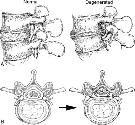
Figure 8. (A) Sagittal and (B) axial illustrations of normal and degenerated lumbar discs. The normal disc functions as a spacer and shock absorber between the vertebral bodies and maintains the space for the nerve roots within the neural foramen. The viscoelastic disc and ligaments limit spinal movement by restricting rotation and translation of the vertebrae. The degenerated disc becomes dehydrated, fissures form, and the disc material fragments. The disc space collapses, causing the neural foramen to become stenotic by bony narrowing and bulging of the annulus and posterior longitudinal ligaments. Reactive bone spurs (osteophytes, traction spurs), which form in an attempt to stabilize the hypermobile spinal segment, can further encroach on the neural foramen.
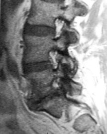
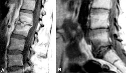
Figure 9. Parasagittal magnetic resonance image demonstrating a degenerated disc at L5-S1, with foraminal stenosis. The rostral neural foramina are normal. Normal nerve roots are surrounded by generous amounts of epidural fat (white signal).
A principal indication for lumbar interbody fusion is severe lumbar disc degeneration, which causes foraminal stenosis and radiculopathies. Collapse of the disc space decreases the cephalocaudal height of the neural foramen. The foraminal stenosis is further accentuated by bulging of the annulus posteriorly, where it buckles into the neural foramen, impinging upon the nerve root along the entire course of the neural foramen (Fig. 8 and Fig. 9). Foraminal stenosis is best imaged with parasagittal MR imaging studies through the neural foramen (Fig. 9).
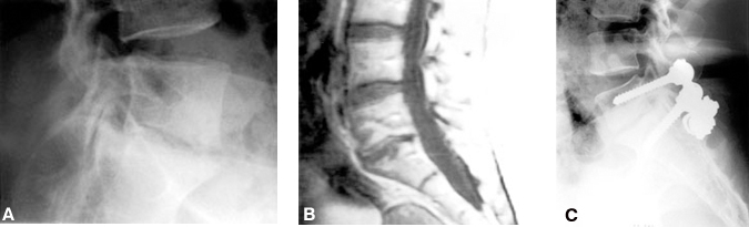
A complete facetectomy may be required to open a stenosed neural foramen adequately. A partial foraminotomy that spares the facet is inadequate treatment for foraminal stenosis when the foraminal encroachment is diffuse. If a complete foraminectomy and facetectomy are performed, the spine is destabilized and a fusion is necessary. Decompression and fusion have commonly been performed through a posterior approach with pedicle screw instrumentation (Fig. 10). Because they allow the disc space to be distracted, interbody fusion cages are an excellent alternative treatment for this pathology. PLIF or ALIF can be used to treat this type of pathology successfully, without the need for a complete facetectomy or wide muscle exposure.
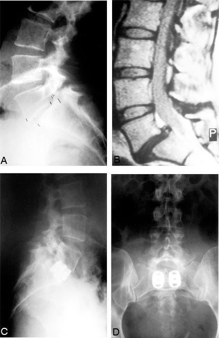
Other indications for lumbar interbody fusion include degenerative lumbar instability (i.e., degenerative spondylolisthesis), congenital spondylolisthesis (Fig. 11), pseudarthrosis of a posterolateral lumbar fusion, or iatrogenic spinal instability (postlaminectomy, postfacetectomy, or postdiscectomy instability) (Fig. 12). Threaded interbody fusion cages should only be used to treat Grade I and II spondylolisthesis. Subluxations greater than Grade II indicate that the spinal ligaments are incompetent and that the cages will likely fail. All of these pathologies may be symptomatic with radiculopathies or cauda equina symptoms related to neural compression, local mechanical lumbar pain from the spinal instability (Fig. 13), or both.21
The most controversial indication for lumbar interbody fusion is mechanical lower back pain associated with disc degeneration but without radicular symptoms, neural compression, or overt spinal instability. The radiographic findings associated with disc degeneration include decreased height of the disc space, bone spurs (i.e., traction spurs), eburnation of the end plates, vacuum discs (gas within the disc space), and neural foraminal stenosis (Fig. 14). On magnetic resonance (MR) imaging, a degenerated disc space appears as a “black disc” due to its loss of water content. The annulus and ligaments bulge. Adjacent vertebral bodies may show characteristic changes in signal intensity (Modic changes) (Fig. 15).15 These changes correspond to the loss of the “shock absorber” and stabilizing functions of the disc after it is injured, loses its hydration, and allows the vertebrae to settle and shift.15

Contraindications
Lumbar threaded interbody fusion cages should not be used if the spinal ligaments are torn or incompetent. The devices depend upon tension applied to the annulus fibrosis and anterior and posterior longitudinal ligaments using distraction to stabilize the implant. If the ligaments are torn or severely stretched, the implants will loosen. Other contraindications include severe osteoporosis (the cages will subside or telescope into the adjacent vertebral bodies);11,18 Grade III, IV, or V spondylolisthesis; vertebral body destruction; active spinal infections (i.e., discitis or osteomyelitis); and disseminated malignancies.
An anterior approach should not be used if there are concurrent free fragment disc herniations, facet hypertrophy, lateral recess stenosis, or central spinal stenosis since posterior pathology cannot be addressed with an ALIF. If a fusion is needed for these problems, a PLIF can be used so that stability is restored through the same incision used for decompression. ALIF also may be contraindicated if the patient has had multiple abdominal operations with adhesions, severe thromboembolic arterial or venous vascular disease, severe atherosclerosis, or an abdominal neoplasm or infection.
PLIF may be contraindicated if a prior discectomy or laminectomy has been performed at the site of the pathology and instability. Scar tissue from a previous spine surgery can make it difficult or impossible to mobilize the dura enough to obtain the exposure needed for a PLIF.
Biomechanical and Structural Properties of Lumbar Threaded Interbody Fusion Cages
The cages are designed with large fenestrations on the cephalad and caudal surfaces and smaller lateral fenestrations to allow bone ingrowth and consolidation through and around the cages. The cages are designed to prevent implant extrusion, implant breakage, disc space collapse, and nonunion.

The threads of the cage are anchored into the vertebral end plates above and below the disc space to resist shear loads and to prevent migration of the cage. The cages are stabilized further by being placed under compressive loads. The third mechanism for stabilizing the implants is the distraction of the disc space, which applies tension to the ligaments and prevents the cage from loosening (Table 2).
In vitro biomechanical studies in destabilized human and animal lumbar spine segments demonstrate that the lumbar threaded interbody fusion cages immobilize the spine much like lumbar pedicle screws.5 Compared to the normal spine, the cages double the stiffness of spinal motion segments. The cages are stronger than a PLIF performed with bone grafts and perform similarly to PLIF with bone grafts and pedicle screws. If the cages are used in conjunction with pedicle screws, the immobilization is markedly superior (Fig. 16).
The cages are able to withstand compressive loads that exceed the physiological loads typical of the lumbar spine.5,11,17 The cages are very strong and unlikely to break (especially compared to pedicle screws). Because of their strength, however, the cages are more likely to subside and partially sink into the adjacent vertebral bodies11,18 especially if the vertebrae are osteoporotic.17,18 Severe osteoporosis may predispose the cage to fail. In such cases, an orthosis or an adjunctive form of internal fixation may be needed.
Surgical Techniques
The steps in the operative procedure for implant placement are similar for both ALIF and PLIF; they primarily differ in the methods used to expose the spine. The steps for inserting the BAK-threaded interbody fusion cage are described to exemplify the process. In most respects, the techniques are similar to those used with other threaded fusion cages. Table 3 lists technical “pearls” that can maximize the success of the surgical implantation of lumbar threaded interbody fusion cages.
Preoperative Planning
CT or MR imaging and precise anteroposterior (AP) and lateral lumbar radiographs (1.5x magnification) are needed to determine the appropriate size of the distraction plugs and implants. A template is used preoperatively to measure the size of the vertebrae and disc space on radiographs, CT scans, and MR images. The normal disc space adjacent to the degenerated disc level is measured to estimate the normal height of the involved level. This information is used to size the distraction plug to ensure that the tension on the spinal ligaments is adequate.
The radiographs, CT scans, and MR images also allow the surgeon to measure the diameter and length of the implants that will fit within the disc space and to measure the size of the pilot holes for the implants in the vertebrae. Axial CT or MR images must be oriented exactly parallel to the vertebral end plates to allow adequate measurement. The pilot holes must fit within the disc spaces without penetrating the annulus anywhere.
Two threaded interbody fusion cages must be placed into each disc space to provide satisfactory stability. A single cage allows excessive rotation (acting like a ball-bearing) and should be avoided. The two cages are inserted symmetrically from the midline with their barrels oriented precisely in an anteroposterior direction (Fig. 17).

Surgical Exposure
Exposure is performed using routine surgical techniques. High-quality fluoroscopy, with AP and lateral imaging, is needed to assess the spine accurately and to judge the trajectory and depth of the implants. Real-time fluoroscopic imaging with precise true AP and true lateral views is essential to avoid malpositioning the cages. This procedure depends on the accuracy of the radiographic positioning; its importance cannot be overemphasized.
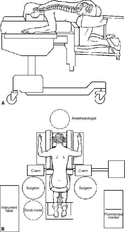
PLIF requires a midline posterior lumbar spinal exposure (Fig. 18). The facets of the involved motion segment are removed to visualize the pedicle, the annulus, the nerve roots, and the foramen clearly (Fig. 19). The epidural veins are cauterized and the dural sac is gently mobilized medially. The pedicles caudal to the disc space to be fused usually must be partially or completely removed with a drill to provide adequate access and to minimize the retraction of the dura. A PLIF retractor is inserted to protect the dura and nerve roots (Fig. 20). The cages are then inserted under fluoroscopic guidance.
Figure 19. A laminectomy and facetectomy are performed to expose widely the involved lumbar disc space. The pedicles caudal to the disc space are removed with a drill. A template is used to measure the entry sites of the cages in the annulus. The annulus is incised at each entry site. With permission from SpineTech.
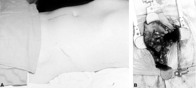
ALIF is performed via a minilaparotomy (4-inch incision)13 (Fig. 21) or laparoscopy.14,16,24,27 The ALIF technique is best suited for the L5-S1 and L4-L5 levels. The latter can be more difficult to expose because more vessels must be mobilized. The aorta, vena cava, and iliac vessels must be retracted to the right side of the spine to access L4-L5.
Exposure of L5-S1 to perform an ALIF is simple (Fig. 22). The small intestines are retracted rostrally and the sigmoid colon is retracted laterally. The posterior peritoneum is incised where it joins the sigmoid mesentery over the lumbosacral spine. The aorta, vena cava, bifurcation of the common iliac vessels, and ureters are identified. The ureters are located laterally running over the iliac vessels at the pelvic brim. The middle sacral artery and vein arise from the bifurcation of the iliac vessels in the midline and overlie the L5-S1 disc space. In most instances, the aorta and vena cava bifurcate into the iliac vessels over the L4-L5 disc space or L5 vertebral body so the L5-S1 disc is easily accessed. A high bifurcation (over L4) may facilitate easy access to the L4-L5 disc space. An abnormally low bifurcation could restrict access to the L5-S1 disc space. The position of the bifurcation of the vessels can usually be judged on the preoperative CT and MR imaging studies.
During the exposure of the L5-S1 disc space, monopolar cauterization is avoided completely to preserve the presacral autonomic plexus. Injury to the autonomic plexus can cause retrograde ejaculation. The middle sacral vessels are ligated with hemiclips and divided sharply. These vessels and the autonomic plexus are then mobilized with blunt dissection using a Kittner dissector and moved laterally from the surface of the L5-S1 disc.
Exposing the L4-L5 disc space usually requires more mobilization and ligation of the vessels than L5-S1 exposure (Fig. 23). The ascending lumbar vessels and the L4 and L5 segmental lumbar vessels must be ligated to allow the aorta, vena cava, and iliac vessels to be retracted sufficiently to expose the entire ventral surface of the L4-L5 disc space. The smaller branches are usually ligated on the left side, and the major vessels are retracted toward the right side so that the veins are retracted less than the arteries. Typically, the veins are more difficult to repair if they are torn or lacerated.
Before the hardware is inserted during ALIF procedures, the exact position of the midline is marked using a Steinmann pin, and a precise AP fluoroscopic image is obtained (Fig. 24). Precise identification of the midline is needed to place the implants symmetrically, to prevent the cages from being offset or displaced, and to avoid penetrating the annulus laterally.
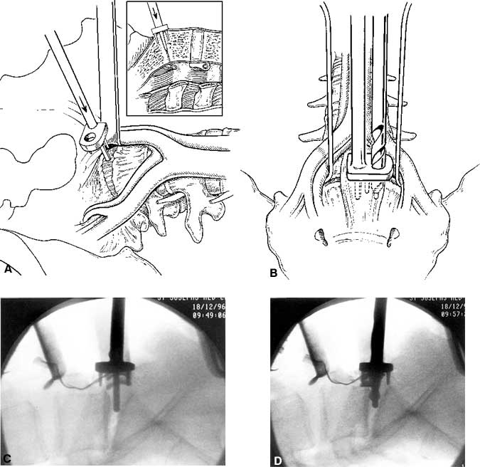
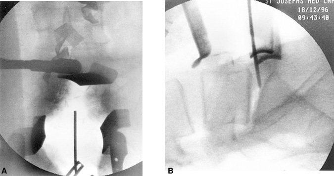
Figure 25. Anterior lumbar interbody fusion at L5-S1. (A) A drill guide is inserted in the midline of the disc. The post of the drill guide is placed into the midline of the disc space. (B) An 8-mm diameter trephine is used to cut initial pilot holes into the disc space. (C) Intraoperative fluoroscopic images after the drill guides have been inserted and (D) the pilot hole drilled. Figure A and B with permission from SpineTech.
During the exposure for ALIF or PLIF, autologous cancellous bone grafts are obtained from the iliac crests to fill the cages. For each cage, 6 to 8 cc of graft material are needed.
Insertion of Cage
The procedures to prepare the pilot holes and to insert the cages are similar for ALIF and PLIF. The cages, which are inserted parallel to each other with their long cylindrical axis oriented anteroposteriorly, should be separated by 4 mm (Fig. 17). Templates are used to mark the entry sites in the annulus. The annulus is incised, and an 8-mm diameter trephine is used to cut a cylinder of disc material from the disc space (Fig. 25).
After the trephine holes are cut bilaterally, additional disc material is removed from the center of the trephine holes using curettes and disc rongeurs (Fig. 26). Lateral fluoroscopy is used to monitor the trajectory for all remaining phases of the procedure.
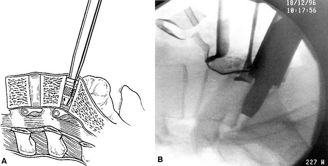
The disc space is sequentially distracted by inserting distraction plugs bilaterally (Fig. 27). These distraction plugs are impacted into the disc space with a mallet. Small distraction plugs are used first and then removed. Progressively larger plugs are inserted until the normal disc space height is restored. The distraction plug must fit snugly into the disc space to attain adequate tension on the annulus and ligaments. The final distraction plug should be seated securely so that the surgeon cannot easily pull the plug out manually with the insertion rod.
If a spondylolisthesis is to be reduced, bilateral sequential distraction is used. The size of the distraction plugs is increased incrementally on each side until normal alignment is achieved. Adequate reduction and ligament tension must be achieved to secure the cages properly in position.

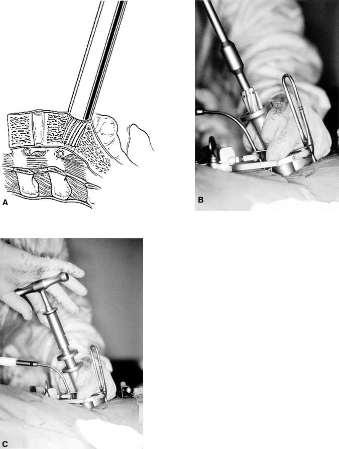
When distraction is adequate, a single distraction plug is left in place on one side and the contralateral cage is placed. A guide tube is positioned to protect the soft tissues and blood vessels superficial to the disc space. Reamers are used to drill manual pilot holes into the disc space. To promote fusion, a portion of the vertebral end plates is removed to expose cancellous bone of the vertebrae. The trajectory of the pilot holes must be exactly parallel to the end plates (Fig. 28).
After the pilot hole is drilled with the reamer, a disc rongeur is used to remove any loose disc material from the bottom of the pilot hole (Fig. 29). Typically, a large plug of soft disc material can be removed from the base of the pilot hole. This maneuver prevents pushing a large piece of disc material into the epidural space when the implant is inserted.
A tap is used to cut the profile of the cage’s threads into the vertebral end plates (Fig. 30). An appropriately sized cage is mounted on a cage insertion tool, and the distal chamber of the cage is packed full of cancellous bone. The cage is inserted into the pilot hole, while care is exerted to avoid stripping the pretapped thread profile from the surrounding bone (Fig. 31). The cage is recessed beneath the surfaces of the vertebral bodies. The large fenestrations of the cage are oriented superiorly and inferiorly, adjacent to the vertebrae. The T-handle of the insertion tool is parallel to the disc space when the cages are in their final orientation. After the first cage is inserted, the distraction plug is removed from the contralateral side and the second cage is inserted using an identical sequence of reaming, tapping the pilot hole, and inserting the cage.

When both cages are inserted in a satisfactory position, they should be recessed beneath the anterior and posterior surfaces of the vertebral bodies. They should be 4 mm apart, exactly parallel, and oriented in a true AP plane, parallel to the vertebral end plates. The final position of the cages is reassessed with AP and lateral fluoroscopy.

After both cages have been positioned, the proximal halves of the cages are packed with cancellous bone (Fig. 32). If desired, a plastic cap can be used to seal the proximal opening of the cage for the PLIF procedure (and usually is) (Fig. 33). For ALIF procedures, the surface of the cage can be covered with bone grafts, which aid the postoperative radiographic assessment of bone bridging.
Wound Closure
Posterior incisions are closed with a routine multilayer closure. After an ALIF has been performed, the mesentery and posterior peritoneum are sutured closed and the abdomen is closed with a routine multilayered closure.
Postoperative Care
Typically, patients are mobilized early and allowed to ambulate within 24 hours of surgery. Bending, twisting, heavy lifting, and heavy exercise are restricted until fusion occurs. Postoperatively, a reinforced lumbar orthosis is usually recommended to help restrict motion while fusion occurs. A thoracic-lumbar-sacral orthosis (TLSO) brace with a thigh extension can be considered, especially if a patient has osteoporosis.
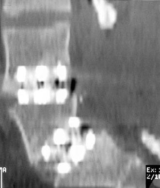
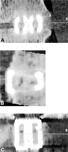
On postoperative radiographs, the cages appear as dense radiopaque material. Bone ingrowth cannot be visualized on plain radiographs. Adequate healing and fusion are assessed by the stability of the hardware, the lack of radiolucencies around the margins of the cages, and the absence of motion at the fixated levels. Reformatted sagittal CT scans can be used to assess the extent of bone ingrowth and consolidation of the bone graft (Fig. 34 and Fig. 35). Typically, fusion requires 3 to 6 months to occur. Patients should be followed for at least 2 years after surgery.
Clinical Outcomes
Clinical data from several sources are available to assess the safety and efficacy of threaded interbody fusion cages.10,12,19,20,27 A clinical prospective multicenter study of 947 patients treated with the BAK device was submitted to the FDA.12,27 The anterior approach was used in 591 cases and a posterior approach was used in 356 cases. Most patients were followed for more than 2 years.

Overall, the fusion rates were excellent: 85.6% at 1 year, 90.6% at 2 years, and 98.3% at 3 years. Two-level procedures had a lower fusion rate than one-level procedures (Table 4). The clinical data also demonstrated significant improvement in pain and function among the patient population.
Complications were divided into major and minor complications. Major complications were rare (2.0%) and included implant migration requiring reoperation (1.2%), great vessel damage, pulmonary emboli, life-threatening pneumonia, sacral fractures with instability, and penetration through the anterior longitudinal ligament. The implants migrated in only 1.2% of patients, usually within 3 months of surgery. The contributing factors were the small size of the implant relative to the height of the disc space, too superficial placement of the implant, and intraoperative stripping of the bone threads.
The rates of other complications are included in Table 5. Complications specific to the posterior approach included a 10% rate of dural tears and a 3.9% rate of unspecified neurological complications. Neurological complications can be minimized by avoiding PLIF for reoperations at disc levels, by mobilizing the dura satisfactorily, and by resecting the pedicles to provide greater exposure to reduce the amount of root retraction. Anterior approaches were more often associated with ileus (2.2%) or atelectasis (1.9%). The incidence of retrograde ejaculation after an anterior approach was 1.9%. This complication can be minimized by avoiding monopolar cauterization and by preserving the autonomic plexus on the surface of the lumbosacral disc spaces.
In no case did the structural integrity of the implant fail. The rate of device-related reoperations was low (4.4%). One-third of the reoperations were performed early (within 3 months), typically for removing or repositioning a device that had migrated. Two-thirds of reoperations were performed late, primarily for additional stabilization to relieve ongoing pain.
Charles Ray20 has published the results of a clinical trial with 236 patients treated with the Ray Threaded Fusion Cage according to an FDA-IDE protocol for one- or two-level lumbar degenerative disc disease. The clinical results were excellent. The fusion rate was 96%, and 86% of patients had satisfactory clinical relief of their back or radicular pain or of both.20 The complications were similar to those observed in the BAK implant study.
Two clinical studies have compared threaded interbody fusion cages inserted using a PLIF approach to 360° fusion with pedicle screws (i.e., anterior interbody grafting and posterior pedicle screws).10,19 These studies demonstrated significant cost reductions using the threaded interbody cages. The mean cost difference was $14,639 per case. Patients treated with posterior threaded interbody fusion cages also had reduced hospital stays (3.5 vs 5.3 days), briefer operations (120 vs 250 min), less blood loss (300 vs 900 cc), and less donor site pain (17% vs 45%). More patients also had returned to work within 3 months (47% vs 0%).10 The results of these two clinical studies are not surprising since they compare treatment with a single approach to treatment with two incisions and two separate operative approaches. However, both forms of treatment are used to treat the same pathologic processes so the comparison seems reasonable.
Future Developments
The surgical results from lumbar interbody fusion will be further enhanced by using minimally incisional endoscopic techniques to insert the cages14,16,24,28,29 and by eliminating complications related to bone graft harvesting by using bone morphogenic protein to induce bone healing into and through the cages (Fig. 35).22 These advances have the potential to shorten recovery time, reduce operative morbidity, and improve clinical outcomes even further. The clinical evaluation of both of these modalities has already commenced, and the results of these experimental studies will be available in the near future.
References
- Bagby GW: Arthrodesis by the distraction-compression method using a stainless steel implant. Orthopedics 11:931-934, 1988
- Branch CL, Jr.: The case for posterior lumbar interbody fusion. Clin Neurosurg 43:252-267, 1996
- Brantigan JW, Steffe AD: A carbon fiber implant to aid interbody lumbar fusion: Two year clinical results in the first 26 patients.Spine 18:2106-2117, 1993
- Brantigan JW, Steffe AD, Geiger JM: A carbon fiber implant to aid interbody lumbar fusion: Mechanical testing. Spine 16:277-282, 1991
- Brodke DS, Dick JC, Kunz DN, et al: Posterior lumbar interbody fusion. A biomechanical comparison, including a new threaded cage. Spine 22:26-31, 1997
- Cloward RB: The treatment of ruptured lumbar intervertebral discs by vertebral body fusion. J Neurosurg 10:154-168, 1953
- Collis JS: Total disc replacement: A modified posterior lumbar interbody fusion. Report of 750 cases. Clin Orthop 193:64-67, 1985
- Dickman CA, Fessler RG, MacMillan M, et al: Transpedicular screw-rod fixation of the lumbar spine: Operative technique and outcome among 104 cases. J Neurosurg 77:860-870, 1992
- Dickman CA, Yahiro MA, Lu HTC, et al: Surgical treatment alternatives for fixation of unstable fractures of the thoracic and lumbar spine: A meta-analysis. Spine 19:S2266-S2273, 1994
- Hacker RJ: Comparison of interbody fusion approaches for disabling low back pain. Spine 22:660-666, 1997
- Jost B, Lund T, Oxland T, et al: Three-dimensional stability and axial settling of interbody cages: A comprehensive in vitro evaluation. Vancouver, BC; North Am Spine Society, 1996
- Kuslich SD, Ahern JW, Dowdle JD: The BAK method of lumbar interbody fusion-two year followup results. Vancouver, BC; North Am Spine Society, 1996
- Mayer HM: A new microsurgical technique for minimally invasive anterior lumbar interbody fusion. Spine 22:691-700, 1997
- McAfee PC, Regan JR, Zdeblick T, et al: The incidence of complications in endoscopic anterior thoracolumbar spinal reconstructive surgery. A prospective multicenter study comprising the first 100 consecutive cases. Spine 20:1624-1632, 1995
- Modic MT, Steinberg PM, Ross JS, et al: Degenerative disk disease: Assessment of changes in vertebral body marrow with MR imaging. Radiology 166:193-199, 1988
- Onimus M, Papin P, Gangloff S: Extraperitoneal approach to the lumbar spine with video assistance. Spine 21:2491-2494, 1996
- Oxland TR, Kuslich SD, Kohrs DW, et al: The BAKTM interbody fusion system: Biomechanical rationale and early clinical results, in Margulies JY, et al (eds): Lumbosacral and Spinopelvic Fixation. Philadelphia: Lippincott-Raven, 1996, pp 545-561
- Oxland TR, Lund T, Jost B, et al: The relative importance of vertebral bone density and disc degeneration in spinal flexibility and interbody implant performance. An in vitro study. Spine 21:2558-2569, 1996
- Ray CD: Threaded fusion cages for lumbar interbody fusions. An economic comparison with 360° fusions. Spine 22:681-685, 1997
- Ray CD: Threaded titanium cages for lumbar interbody fusions. Spine 22:667-680, 1997
- Rolander S: Motion of the lumbar spine with special reference to the stabilizing effect of posterior fusion. Acta Orthop Scand 90:1, 1996
- Sandhu HS, Kabo JM, Turner AS, et al: rhBMP-2 augmentation of titanium fusion cages for experimental anterior lumbar fusion. Vancouver, BC; North Am Spine Society, 1996
- Simmons JW: Posterior lumbar interbody fusion with posterior elements as chip grafts. Clin Orthop 193:85-89, 1985
- Southerland SR, Remedios AM, McKerrell JG, et al: Laparoscopic approaches to the lumbar vertebrae. Spine 20:1620-1623, 1995
- Toth JM, Turner AS, Kabo JM, et al: Porous tantalum metal as a biologically advantageous spinal fixation material. Vancouver, BC; North Am Spine Society, 1996
- Yuan HA, Garfin SR, Dickman CA, et al: A historical cohort study of pedicle screw fixation in thoracic, lumbar and sacral spinal fusions. Spine 19:S2279-S2296, 1994
- Yuan HA, Kuslich SD, Dowdle JA, Jr., et al: Prospective Multi-Center Clinical Trial of the BAKTM Interbody Fusion System. Minneapolis: SpineTech, Inc., 1997
- Zucherman JF, Hsu K, Implacito D: Instrumented and transperitoneal laparoscopic fusion, in Margulies JW, et al (eds):Lumbosacral and Spinopelvic Fixation. Philadelphia: Lippincott-Raven, 1996, pp 579-585
- Zucherman JF, Zdeblick TA, Bailey SA, et al: Instrumented laparoscopic spinal fusion. Preliminary results. Spine 20:2029-2035, 1995