
Preoperative Helical CT Angiography for C1-2 Transarticular Screw Placement: A New Technique
Nicholas Theodore, MD†§
Shahram Partovi, MD‡
Matthew T. Walker, MD‡*
Phil Saba, MD‡
Volker K.H. Sonntag, MD†
†Divisions of Neurological Surgery and ‡Neuroradiology, Barrow Neurological Institute, St. Joseph’s Hospital and Medical Center, Phoenix, Arizona
Current Addresses:
§Division of Neurosurgery, Naval Medical Center, San Diego, CA
*Division of Neuroradiology, Northwestern Memorial Hospital, Chicago, Illinois
Abstract
Injury to the vertebral artery during transarticular screw placement can have disastrous consequences. A new radiologic technique using state-of-the-art computerized tomographic angiography as a preoperative adjunct can help decrease the risk of injuring the vertebral artery.
Key Words: computed tomographic angiography, transarticular screw, vertebral artery
Numerous techniques and radiologic protocols have been developed to predict which patients can safely undergo placement of a transarticular screw. None of these strategies, however, address the true arterial morphology and its relationship to the neighboring bony anatomy. This article reviews a current method of preoperative evaluation and describes a new system that could help decrease the potential of injuring the vertebral artery during the placement of C1-2 transarticular screws.
Current Imaging of the C1-2 Complex
Plain radiography of the cervical spine with and without dynamic views is the diagnostic standard for the evaluation of all atlantoaxial pathologies. Once a pathology has been diagnosed, magnetic resonance (MR) imaging and computerized tomography (CT) are both useful adjuncts. MR imaging is valuable because of its ability to delineate injuries to the transverse ligament.[2,4] Pure ligamentous injuries are incapable of healing without internal fixation and are treated surgically. In contrast, fractures and avulsions of the tubercle for insertion of the transverse ligament have a high incidence of healing when treated with a rigid orthosis.[2,4] MR imaging can help to identify appropriate surgical candidates, but it provides no detailed information about regional bony anatomy.[7,9] As a preoperative adjunct, MR angiography elucidates the morphology and course of the vertebral arteries as well as the presence of an arterial dissection. The latter is a common sequela in patients with a fractured or unstable cervical spine related to trauma.
CT, however, is without a doubt the most important modality when determining a patient’s suitability for the placement of transarticular screws. Preoperative CT scanning with appropriate reconstructions in the sagittal and coronal planes allows the C2 transverse foramen and C1-2 facet joint to be evaluated comprehensively. Using a protocol described by Paramore, Dickman, and Sonntag,[10] all patients at the Barrow Neurological Institute who underwent placement of a C1-2 transarticular screw since 1994 have undergone preoperative evaluation of the atlantoaxial region. This evaluation follows traditional axial slices with coronal and sagittal reconstructions.
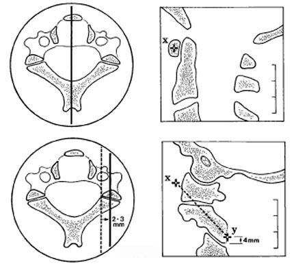
A special screw trajectory is reconstructed by placing a marker on the midportion of the image of the anterior arch of C1 (corresponding to the target seen on intraoperative fluoroscopy during surgery, Fig. 1). The sagittal image is moved laterally until the image shown is 2 to 3 mm from the lateral border of the spinal canal (as seen on inset axial image). A second marker is then placed on the sagittal image about 4 mm superior to the C2-3 facet complex, which corresponds to the entry point of the screw. The two markers are connected, and reconstruction is performed in the plane described by this line and the lateral axis.
This protocol is a useful preoperative adjunct and can predict which patients are at risk for potential vascular injury. However, it provides no information about the vertebral artery and its intimate relationship with the surrounding bone. CT angiography is a relatively new modality that uses high-speed scanners with nonionic contrast administration to evaluate vascular structures. Vessels can be shown in relationship to their surrounding bony confines. This technique has not been described previously as a method to assess the feasibility of transarticular screw placement before surgery. In addition to preoperative assessment, this technique can be used in conjunction with image-guided technology to obtain a real-time evaluation of the course of the vertebral artery during placement of transarticular screws or during any other procedure that could place vascular structures at risk.
CT Angiographic Protocol of C1-2 Complex
A General Electric LightSpeed multi-array detector CT scanner (General Electric Company, Milwaukee, WI) is used to perform a helical CT scan of the craniocervical junction, from midC3 through the foramen magnum. Scanning is performed with a tube rotation time of 1 second. Slices are 1.25-mm thick at 1-mm intervals, resulting in an overlap of 0.25 mm. High-quality mode is used and results in a pitch of 3. Visipaque 320 (100 ml, Nycomed, Inc., Princeton, NJ) is administered intravenously, and scanning is performed with a 9- to 16-second delay based on the patient’s age and cardiac status. Postprocessing includes three-dimensional reconstructions of the vertebral arteries as well as sagittal and coronal reformatted images of the bony structures. Multiplanar volume reconstruction images are used to combine the vertebral arteries with the bony structures to obtain a representation of the anatomic interrelationships.
Illustrative Cases
Case 1
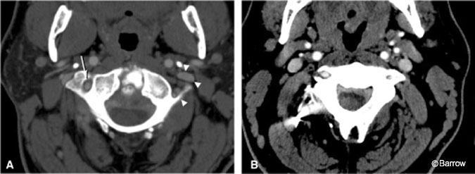
A 40-year-old male who suffered an odontoid fracture 20 years ago and was treated with a Gallie-type posterior fusion sought treatment for severe neck pain, Lhermitte’s sign, and episodes of paresthesias and weakness with neck movement. MR imaging studies demonstrated pannus behind the body of C2 and evidence of an unfused type II odontoid fracture. Because the anterior compression was minimal, it was believed that posterior arthrodesis of the atlantoaxial complex would be sufficient to treat his chronic instability. Preoperative CT angiography showed that the vertebral artery was absent on the left (Fig. 2). Therefore, we decided to place a single transarticular screw on the left to avoid the risk of compromising the patient’s entire posterior circulation by placing screws bilaterally. A single transarticular screw satisfactorily immobilizes the atlantoaxial complex.[12] In this case, CT angiography simultaneously provided a clear picture of the relevant arterial and bony anatomy, and placement of a single screw on the side without a vertebral artery avoided a potentially disastrous complication. Despite his previous failed fusion, the patient developed a solid arthrodesis and recovered completely.
Case 2
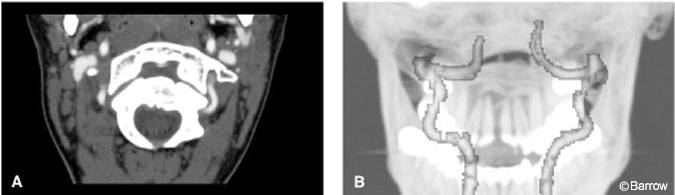
An 18-year-old female with a history of suboccipital headaches underwent plain radiography, which showed an abnormality in the cervical spine. The patient had an os odontoideum, which was unstable with 15 mm of movement on flexion-extension radiographs. CT angiography demonstrated normal vertebral arteries bilaterally (Fig. 3). The patient underwent placement of a single transarticular screw on the left because the bony anatomy on the right was inadequate to support a screw. The patient developed a solid C1-2 fusion, and her preoperative symptoms resolved completely.
Case 3
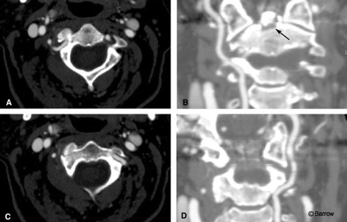
A 70-year-old woman sustained a fracture at the base of the dens and right lateral mass of C2 in a motor vehicle accident. She was treated conservatively at an outside institution with rigid cervical orthosis. On follow-up examination, she still had neck pain. Flexion-extension radiography showed atlantoaxial instability. CT angiography demonstrated codominant vertebral arteries (Fig. 4). Because of the bony anatomy, the patient underwent placement of a single right-sided transarticular screw and ultimately developed a solid fusion. Her neck pain resolved completely.
Discussion
CT angiography offers an innovative way to image the critical vascular structures of the craniovertebral junction while preserving the detail of bony structures that is lacking on MR angiography. CT angiography will become an important part of the preoperative assessment as well as intraoperatively in conjunction with image-guided technology of patients undergoing transarticular screw placement and other spinal procedures that place vascular structures at risk. In addition to being relatively noninvasive, CT angiography offers much quicker processing and postprocessing than MR imaging.
References
- Coric D, Branch CL, Jr., Wilson JA, et al: Arteriovenous fistula as a complication of C1-2 transarticular screw fixation. Case report and review of the literature. J Neurosurg 85:340-343, 1996
- Dickman CA, Sonntag VK: Injuries involving the transverse atlantal ligament: Classification and treatment guidelines based upon experience with 39 injuries. Neurosurgery 4:886-887, 1996
- Goel A, Gupta S: Vertebral artery injury with transarticular screws. J Neurosurg 90:634-640, 1999
- Greene KA, Dickman CA, Marciano FF, et al: Transverse atlantal ligament disruption associated with odontoid fractures. Spine 20:2307-2314, 1994
- Grob D, Magerl F: Dorsal spondylodesis of the cervical spine using a hooked plate [German]. Orthopade 16:55-61, 1987a
- Grob D, Magerl F: Surgical stabilization of C1 and C2 fractures [German]. Orthopade 16:46-54, 1987b
- Haid RW, Jr.: C1-C2 transarticular screw fixation: Technical aspects. Neurosurgery 49:71-74, 2001
- Jeaneret B, Magerl F: Primary posterior fusion C1/2 in odontoid fractures: Indications, technique, and results of transarticular screw fixation. J Spinal Disord 5:464-475, 1992
- Mirvis SE: MR imaging for assessing acute vertebral trauma. Semin Musculoskelet Radiol 2:27-44, 1998
- Paramore CG, Dickman CA, Sonntag VKH: The anatomical suitability of the C1-2 complex for transarticular screw fixation. J Neurosurg 85:221-224, 1996
- Prabhu VC, France JC, Voelker JL, et al: Vertebral artery pseudoaneurysm complicating posterior C1-2 transarticular screw fixation: Case report. Surg Neurol 55:29-33, 2001
- Song GS, Theodore N, Dickman CA, et al: Unilateral posterior atlantoaxial transarticular screw fixation. J Neurosurg 87:851-855, 1997
- Wright NM, Lauryssen C: Vertebral artery injury in C1-2 transarticular screw fixation: Results of a survey of the AANS/CNS section on disorders of the spine and peripheral nerves. American Association of Neurological Surgeons/Congress of Neurological Surgeons. J Neurosurg 88:634-640, 1998