
Advances in the Understanding of Spinal Biomechanics Through Experimental Research
Author
Neil R. Crawford, PhD
Spinal Biomechanics Research Laboratory, Division of Neurological Surgery, Barrow Neurological Institute, St. Joseph’s Hospital and Medical Center, Phoenix, Arizona
Abstract
Surgeons and researchers are often curious about the biomechanical behavior of the spine. For example, which fixation device stabilizes the spine most rigidly? Which fixation device is least likely to fail by screw pullout? How much cranial settling is associated with lateral spreading of the atlas? Several experimental methods are available to researchers to address these and other questions. This article highlights five different methods used in researching spinal biomechanics: flexibility testing, load-to-failure (strength) testing, fatigue (endurance) testing, physical modeling, and mathematical modeling. The conditions in which each technique should be used and published examples of each method are provided.
Key Words: biomechanics, spine
Biomechanics researchers collaborate with surgeons in the laboratory to perform experiments that offer insights into the biomechanical behavior of the spine. Such insights provide surgeons with a rationale for which surgical techniques are likely to work best in treating patients. They also enhance the basic understanding of how the spine functions.
Different research techniques are available to address questions about spinal biomechanics. Previous publications have focused on the descriptions and usage of biomechanical parameters.[2] In contrast, this article offers an overview of several different research techniques often applied to the study of spinal biomechanics. The type of questions best addressed by each technique and the information that can be obtained are described.
Flexibility Testing
In a flexibility test, a prechosen load is applied to a cadaveric spine while the displacement is recorded. Hydraulic systems, pneumatic systems, or dead weights are used to apply the loads, and optical or goniometric systems are used to record movement. Applied loads are within the range of loads that the body is capable of exerting in vivo so that the specimen is not damaged. Specimens therefore can be studied in several directions of loading (e.g., flexion, extension, lateral bending, axial rotation) and in one or more surgical conditions (e.g., normal, injured, fixated).
Flexibility tests are performed using human cadaveric models or animal models. Human cadaveric models are favored because the information obtained from tests is easily generalized to living subjects given certain assumptions about the lack of contribution from muscles and lack of regenerative abilities. Conclusions based on animal models are less accurate because their anatomy and tissue properties differ from those of humans. However, animal models can answer questions that are impossible to address in a human model, for example, the effect on spinal biomechanics of healing, drug interactions, or other processes requiring a system that must be alive for a period before the flexibility test is performed.

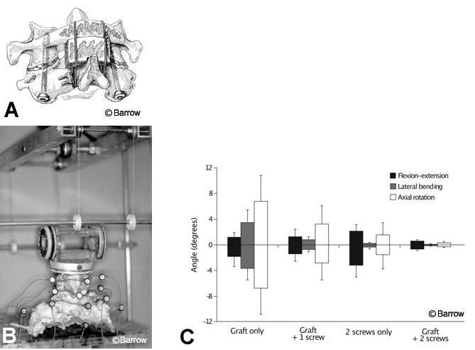
Research questions best addressed by flexibility tests are comparisons among different treatments (e.g., different fixation devices, different types of resection, different injuries) in terms of how much or how little the spine moves during different types of natural loading. The following is an example of a question addressed by a published flexibility testing experiment: What is the difference in the stability of C1-C2 when different combinations of posterior cables and grafts and one or two transarticular screws are used for fixation after odontoidectomy (Fig. 1A)?[7] In this study, human cadaveric spines were loaded to induce flexion, extension, lateral bending, and axial rotation while motion from optical markers was measured (Fig. 1B). The use of nondestructive loads allowed several different conditions to be tested in the same specimens (i.e., two screws alone, graft alone, one screw plus graft, two screws plus graft). The results showed that increasing the points of fixation improved stability significantly. Cable and graft most effectively resisted flexion and extension, but transarticular screws most effectively resisted lateral bending and axial rotation (Fig. 1C). This experiment provided surgeons with information about the degree of instability to expect after stabilizing C1-C2 when using any of these possible combinations of fixation. It also improved understanding of the functions of transarticular screws and posterior cables and grafts in this construct.
Load-to-Failure Tests
Instead of studying how the spine responds within the physiologic ranges of loads and movements, it is often interesting for researchers to study the load required for failure. For example, when a spine segment fixated with anterior screws and a plate is loaded severely, do the screws break or pull out If the screws break, it might be beneficial to increase their diameter or to manufacture screws from a stronger material. If the screws pull out, it might be beneficial to alter their insertion angle or the depth of their threads.
In a load-to-failure test, the specimen deformation is recorded as a function of applied load. Hydraulic materials-testing machines with built-in displacement transducers are the most common method for applying load and recording deformation. From this recording, the researcher can measure failure parameters. The most important parameter is the ultimate strength, which is the highest load endured during failure. The way in which failure occurs (e.g., screw pullout or screw breakage) is an important qualitative observation.
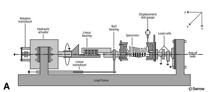
Load-to-failure tests can be categorized into two types: those using cadaveric tissues and those using synthetic models. Load-to-failure tests using cadaveric tissues are often performed on spines devoid of fixation hardware to gain understanding of the strength of spinal structures. For example, in one study the entire cervical spine was loaded to failure during torsion to determine which part of the cervical spine-upper or lower-was more susceptible to rotational failure.[5] Specimens always failed first at C1-C2. After the failed level was removed and the remainder of the cervical spine was refixtured, specimens failed at a higher load in the lower cervical region (Fig. 2).
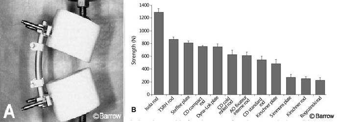
Load-to-failure tests using synthetic models are often used to define the strength of a fixation device without having the findings confounded by the inconsistent strength of the bone in which it would normally be inserted. A common method of studying the failure of implants is to use two ultrahigh molecular weight polyethylene pucks to model a corpectomy. The instrumentation is fastened and loaded to failure by compressing the pucks together with the piston of a hydraulic materials testing machine. One study used such a model to compare 12 different pedicle screw-rod and pedicle screw-plate constructs (Fig. 3). Certain devices failed at much higher loads than others. Such information is important because lumbar pedicle-screw systems sometimes must sustain large loads in vivo. However, stronger implants are not necessarily better at eliminating movement associated with smaller nondestructive loads and would not necessarily achieve better fusion outcomes. A desirable device would perform well in both a load-to-failure test and a flexibility test.
Fatigue Testing
Spinal fixation hardware sometimes loosens or fails. These complications may occur because the strength of an implant was exceeded. More often, however, failure or loosening occurs because the implant was stressed so repetitively that it eventually stretched or broke from fatigue. Therefore, constructs and implants are tested to determine their susceptibility to damage from fatigue. Fatigue tests can be categorized as fatigue to failure or intermediate fatigue.
Intermediate fatigue is the practice of using fatigue as a treatment in a flexibility testing experiment. Flexibility tests would be performed before and after fatigue is induced to elucidate how much stability was lost because of fatigue. Because it is part of a flexibility test, this type of fatigue is usually tested in an animal or human cadaveric model. The flexibility testing apparatus doubles as a fatigue apparatus for applying fatigue loads.
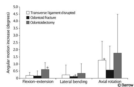
An example of intermediate fatigue is a study in which a posterior interspinous cable-graft construct alone (Fig. 1A) was used to stabilize three different injuries to the upper cervical spine: odontoid fracture, ruptured transverse ligament, and odontoidectomy.[1] Flexibility tests were performed on each specimen immediately after the graft was placed. Specimens received 6000 cycles of loading and unloading to a moderate physiologic load, and flexibility tests were repeated. Flexibility and fatigue tests were performed with a string-and-pulley setup identical to that shown in Figure 1B. The interspinous cable-graft construct loosened when used to stabilize any of the three injuries (Fig. 4). This finding supported the authors’ conclusion that an interspinous cable-graft construct should probably be accompanied by an adjunctive stabilizing technique such as transarticular screws or a halo brace to ensure C1-C2 fusion.
Fatigue-to-failure testing often uses the same plastic-puck corpectomy model described for load-to-failure tests (Fig. 3A). Fatigue loads are applied using the piston of a hydraulic materials-testing machine. A load is selected that is well below the strength of the construct based on the load-to-failure tests. The model is cycled between this load and a load near zero at a rate as high as 20 cycles per second. Cycling continues until failure or until a prechosen maximum number of cycles is met (usually 1 to 10 million cycles). If the maximum number of cycles (“runout”) is reached, the load does not exceed what is known as fatigue strength, and it is assumed that the model will never fail at that load. Several loads are commonly studied to determine the relative fatigue strengths of implants being compared.
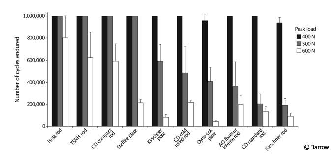
The study of Cunningham et al.[3] used as an example of load-to-failure testing in synthetic models (Fig. 3) also included fatigue-to-failure experiments. The same type of constructs studied in the load-to-failure tests were cycled for as many as 1 million times at three different peak loads to determine which of 10 pedicle-screw constructs had adequate fatigue strength to endure each load. Certain systems were much more resistant to fatigue than others (Fig. 5).
Such findings help surgeons to select instrumentation systems. The fusion implant system selected should not fail before fusion occurs. In the case of an artificial disk, the implant must last the remainder of a patient’s life. It is difficult to correlate the number of cycles from a high-frequency fatigue test to the number of weeks or years of daily in vivo usage of a spinal implant. However, this value can be estimated based on a particular patient’s lifestyle (e.g., how many times the patient moves from sitting to standing each day, how much the patient walks, and so on). Probably a more objective approach is to compare the relative fatigue strength of a particular device to that of a clinically established device to ensure that the device in question is reliable under fatigue.
Physical Modeling
Experiments in which flexibility, load to failure, and fatigue endurance are studied typically compare different treatments of the spine (e.g., stability after different injuries, fixation devices, surgical resections, diseases, and so on). If a hypothesis about the basic functions of the spine is of interest, physical models of the spine are sometimes appropriate. Many effective physical models look nothing like an actual spine but simplify the function of interest as much as possible to provide straightforward data to support or discredit the hypothesis.

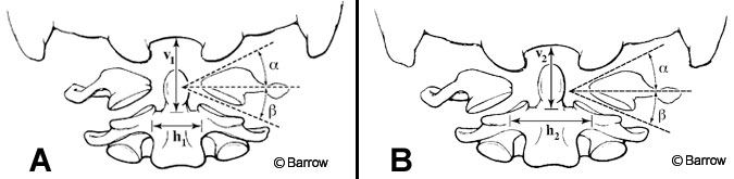
An example of a physical model is the simplification of the upper cervical spine complex into two planar wedges that are being compressed (Fig. 6).[6] This model was used to explain why the ring of C1 can spread during axial compression of the head, especially when the ring is not intact. Static engineering analysis of the wedge model was compared to experimental data in which upper cervical spine specimens were compressed while the spread of the C1 ring was recorded. The simplified model accurately predicted the amount of spreading that actually occurred experimentally.
In this physical model, as in other effective published physical models, experimental findings are also collected to verify or discredit the hypothesis of the physical model. When such a physical model-which tends to be easier to understand than the actual complex interactions of the various muscles, joint articulations, ligaments, and disk-is consistent with experimental findings, it improves understanding of the biomechanical function of the spine.
Mathematical Modeling
The methods described earlier are usually adequate to elucidate the biomechanical response of the spine. In some cases, however, a question about biomechanical behavior may be impossible to answer from an experiment using the common models. For example, how could an experiment be performed to determine the effect of removing the disc nucleus while leaving the annulus intact if it is impossible to remove the nucleus without transecting the annulus? In such cases, mathematical modeling is a useful alternative.
Finite-element modeling is the most common mathematical method of modeling spinal biomechanical behavior. In this method, the distribution of forces to a three-dimensional detailed representation of the bony architecture of the spine is determined by iterative equations run on a computer. The finite-element method is especially effective in predicting locations of high stress on a vertebra.
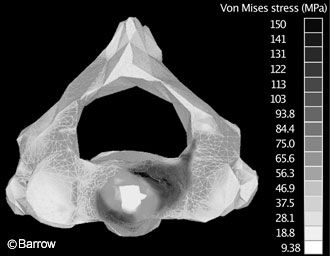
A study by Graham et al.[4] exemplifies a finite-element model. They identified stress and fracture patterns on C2 when different types of loads were applied to the odontoid.
To determine the fracture patterns experimentally would have required impossibly extensive instrumentation of the surface of the vertebra with strain gauges. Using the finite-element method, the response to stresses at one point on the vertebra could be predicted mathematically based on assumptions about the material properties of the underlying bone. The authors showed that loading in pure extension was likely to lead to a Type III odontoid fracture whereas loads applied at an angle of more than 15 degrees off the sagittal plane generated stress patterns consistent with Type II odontoid fractures (Fig. 7).
Conclusion
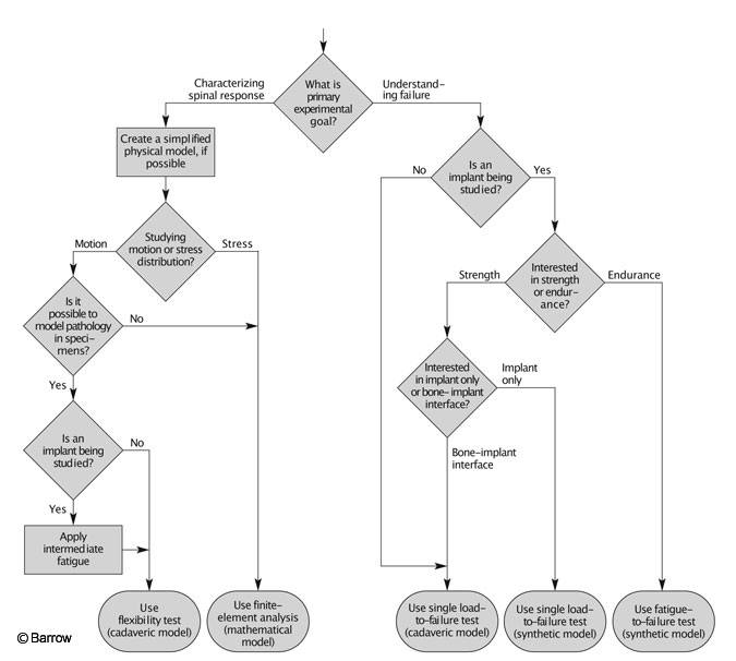
Researchers have many options when planning experiments to investigate spinal biomechanics: flexibility tests, load-to-failure tests, fatigue tests, physical models, or computer models. Another consideration is whether to use a synthetic or cadaveric model. An experiment could be planned that would use one, some, or all of the techniques outlined in this article. Each technique offers different information, and the appropriate technique depends on the experimental goals. The thought process for selecting appropriate experimental design to meet the desired goals can be simplified into an algorithm (Fig. 8).
References
- Crawford NR, Hurlbert RJ, Choi WG, et al: Differential biomechanical effects of injury and wiring at C1-C2. Spine 24:1894-1902, 1999
- Crawford NR, Sonntag VKH, Dickman CA: Principles of spinal biomechanics, in Crockard A, Hayward R, Hoff JT (eds): Neurosurgery: The Scientific Basis of Clinical Practice. Oxford: Blackwell Science Ltd., 2000, pp 1073-1092
- Cunningham BW, Sefter JC, Shono Y, et al: Static and cyclical biomechanical analysis of pedicle screw spinal constructs. Spine 18:1677-1688, 1993
- Graham RS, Oberlander EK, Stewart JE, et al: Validation and use of a finite element model of C-2 for determination of stress and fracture patterns of anterior odontoid loads. J Neurosurg 93 (Suppl 1):117-125, 2000
- Myers BS, McElhaney JH, Doherty BJ, et al: The role of torsion in cervical spine trauma. Spine 16:870-874, 1991
- Naderi S, Crawford NR, Melton MS, et al: Biomechanical analysis of cranial settling after transoral odontoidectomy. Neurosurgical Focus 6:Article 7, 1999
- Naderi S, Crawford NR, Song GS, et al: Biomechanical comparison of C1-C2 posterior fixations. Cable, graft, and screw combinations. Spine 23:1946-1956, 1998