
Physical Aspects of Stereotactic Radiosurgery
Jeffrey A. Fiedler, MSc
Gamma Knife Center, Barrow Neurological Institute, Mercy Healthcare Arizona, Phoenix, Arizona
Abstract
Stereotactic radiosurgery is a demanding treatment modality that depends upon the accurate and precise geometric and dosimetric delivery of potentially damaging levels of radiation. To ensure the availability of safe, reproducible, and clinically efficacious treatment, all of the equipment utilized must be thoroughly examined and continually tested to characterize and monitor its performance, as well as to detect problems as far in advance as possible before patient care might be affected. Medical Physics is the specialty and field of practice responsible for technical matters related to stereotactic radiosurgery. This article briefly describes the education, clinical training, and experience of a typical Medical Physicist. How this knowledge is applied to transform physical formulae, mathematical models, and technical specifications into a safe, accurate, reliable, and relatively simple noninvasive procedure for the treatment of deep or inoperable intracranial lesions is emphasized. A description of a typical Gamma Knife treatment is outlined to provide the reader with a glimpse of Gamma Knife procedures.
Key Words : Gamma Knife, medical physics, stereotactic radiosurgery
Initially conceived as a noninvasive alternative to open neurosurgery,8 stereotactic radiosurgery has evolved into a therapeutic modality now used as both postoperative adjuvant treatment and to boost radiation doses in conjunction with conventional external beam radiation therapy.6 Rapid advances in technology, especially those in computing, have profoundly affected procedures followed in the delivery of stereotactic radiosurgery.2 Thorough acceptance-testing and commissioning of the equipment, its continuous monitoring, and evaluation of the device’s performance and beam characteristics are critical to accurate delivery of the high-dose levels used in radiosurgical techniques.

This article briefly describes each of the physics-related aspects of licensing, commissioning, and operating a Gamma Knife. Selection and use of equipment as well as analysis of data are discussed to provide the reader an overview of some of the medical-physics issues dealt with in establishing a Gamma Knife-based stereotactic radiosurgery program.
Role of Medical Physicists
Physicians who practice stereotactic radiosurgery usually lack the necessary training in mathematics and physics, the technical expertise, experience, dedicated specific technical interest, and time required to comprehensively perform labor-intensive equipment and beam testing. The person assigned these duties must be thoroughly familiar with medical applications of ionizing radiation in addition to having an educational background that provides a high level of facility in the subject areas outlined above. Medical Physicists specializing in therapeutic radiological physics, who usually have graduate degrees in biomedical engineering, nuclear engineering, nuclear physics, medically applied physics or biophysics and experience with the procedures and operations of radiation oncology clinics, easily satisfy these requirements. Many Medical Physicists take examinations analogous to those completed by physicians to attain certification in their subspecialty area of practice from the American Board of Medical Physics (ABMP), the American Board of Radiology (ABR), or both. These credentials are important in states that license the practice of Medical Physics since licensure and hence the ability to work in the profession may be denied without them. Certification by the ABR, a medical specialty board that also certifies physicians, confers eligibility for full membership in the American College of Radiology and results in a listing in the American Directory of Medical Specialists.
The role of a physicist involved with any stereotactic radiosurgery program may be defined as comprising four major areas: (1) ensuring the safe, proper operation of radiation-emitting devices and all ancillary equipment used in the design and delivery of radiation treatment, (2) collecting and analyzing all relevant radiation-dose data used in calculating radiation-dose distributions and corresponding exposure times, (3) designing treatment plans according to directions provided by the attending neurosurgeon and radiation oncologist, and (4) monitoring the implementation of machine settings during the delivery of treatment to assure compliance with the geometric/timing parameters specified in the treatment plan.
Federal or state agencies require detailed procedures describing how each of these tasks will be achieved. Before any institution is issued a radioactive materials license for medical use of the Cobalt 60 (60Co) source supply associated with any Gamma Knife, documentation of specialized training in the application of ionizing radiation using stereotactic techniques is also required for each medical practitioner who wants to prescribe radiation doses or to be directly involved in the delivery of treatment (Fig. 1). The task of collecting, collating, writing up, and submitting all of this information in the appropriate format to the government agency in charge thus also becomes an important part of a physicist’s duties. This administrative/regulatory aspect of the physicist’s job never ends, since actual licensure marks just the beginning of a whole series of processes directed at maintaining compliance with the terms of the license, for both the site and all authorized users.
Licensure
In the United States, the federal government has jurisdiction over all non-naturally occurring (reactor- and/or cyclotron-produced) radioactive material. However, under the terms of Nuclear Regulatory Commission (NRC) regulation 10 CFR 150, state governments (which have jurisdiction over all naturally occurring radioisotopes and all radiation-producing devices such as x-ray tubes and accelerators located within their geographic boundaries) may enter into an agreement with the NRC to subcontract this function and to administer their own programs for licensing radioactive materials. Arizona has undertaken to follow this route, making it an Agreement State, with the Arizona Radiation Regulatory Agency (ARRA) assigned responsibility for relevant licensing and radiation safety issues.
All ARRA license applications require documentation supporting the qualifications of each person who wishes to prescribe or directly supervise the medical use of the isotope in question. Information concerning licensee self-regulation procedures, facilities and equipment available on site dedicated to or available for use in conjunction with the proposed medical application, and/or its associated quality assurance/radiation safety testing program(s) is also necessary. A complete set of diagrams and calculations upon which the thicknesses of primary and secondary shielding barriers are based also must accompany the license application for those spaces housing the applied-for amount of radioactive material. Data and specifications providing information such as the total average and maximum source activity (emissions per unit time), construction, and housing of the radioactive source(s) to be used also are mandatory.
For the Barrow Neurological Institute’s Gamma Knife, ARRA Medical Teletherapy License 7-424 allows medical use of up to 6600 Ci of60Co activity (2.442 x 10¹⁴ decay events per second, each 1.25 MeV in average energy), with up to 9900 Ci of 60Co permitted on site during reloading. This represents the highest amount of activity licensed for medical use at a single installation in the state.
Prior to delivery and placement inside the Gamma Knife, each radiation source is wiped with a cotton swab, which is then surveyed to confirm the integrity of source encapsulation. At the time of loading, a subset of sources is wipe tested again. When all sources have been loaded, the transport casks and handling equipment used for storage or manipulation of radioactive materials also must be examined carefully to ensure that the treatment site itself has not been contaminated inadvertently during the loading procedure. The new, electrically operated Model B Gamma Knife arrives with its own portable, self-shielded loading machine. The strict isolation provided by this loader significantly decreases the probability of any site contamination when compared with the temporary hot-cell labs constructed on-site for loading of the hydraulically operated Model U Gamma Knife. It also decreases the total time required for loading and reloading operations.
After a Gamma Knife has been fully assembled and loaded, its manufacturer (Elekta Radiosurgery, Inc., Atlanta, GA) completes a variety of device inspections and machine-function tests to ensure that it is operational and working within the set of stringent mechanical and geometric tolerances specified for it at time of purchase, and that a minimum dose-rate of 300 cGy/min† is available at the intersection point of all 201 radiation beams originating from the sources housed within.

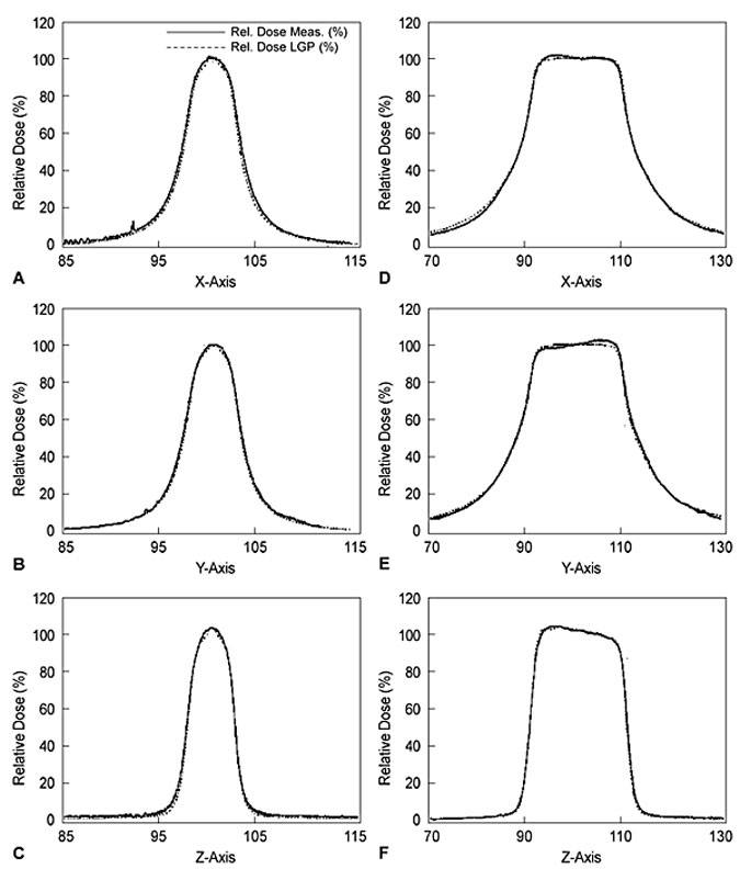
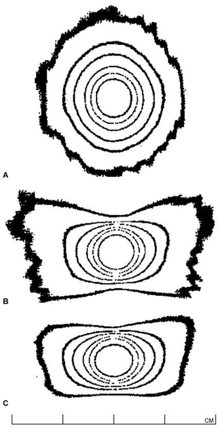
Once the machine has been certified as properly installed and operational by the manufacturer, the Gamma Knife physicist conducts a detailed and comprehensive series of tests.9 (1) The dose-rate at the beam-intersection focus is measured and defined exactly, a procedure known ascalibration.12 (2) The dose distributions delivered by each of the four different beam-defining collimators provided with the unit are fully characterized or mapped (each produces a “sphere” of radiation dose near 4, 8, 14, or 18 mm in diameter, centered at the beam-intersection focus). This beam mapping is accomplished by measuring and graphing radiation dose as a function of position along each of the x (right/left),y (anterior/posterior), and z (superior/inferior) axes (Fig. 2). Graphs showing a select set of equal dose points in each of the axial (x-y), sagittal (y-z), and coronal (x-z) planes, known as isodose plots, are also produced (Fig. 3). (3) The relative output factors for each of the four collimator helmets are determined. The output factor is the ratio of absolute dose delivered per unit time by a specific collimator relative to the dose delivered over the same period of time by the largest available collimator (Table 1). (4) Attenuation of the radiation beam by the interchangeable collimator plugs (which may be used for blocking of selected beam channels to shield normal radiation-sensitive anatomic structures during Gamma Knife treatment) is measured. (5) The geometric accuracy, precision, and reproducibility of the mechanical attachments and accessories used during stereotactic irradiation—which define the treatment coordinates—are confirmed. (6) The three-dimensional spatial correspondence between the beam isocenter, the maximum dose point within the dose-distribution pattern produced by each collimator, and the geometric center of the Gamma Knife’s source-holding hemisphere is evaluated. (7) All of the data measured above are correlated with those stored in the Gamma Knife treatment-planning computer and used to construct the beam models applied during calculation of radiation-dose distributions for individual treatment plans. (8) The accuracy and linearity of the unit’s treatment timing controls are verified. (9) All of the unit’s safety features, including its entry door interlock circuits, emergency treatment interrupt and stop switches, patient audio and visual communication links between the treatment room and control area, and all of the facility radiation monitors, are tested thoroughly.
Diode dosimeters also are sufficiently small not to change the effects of any field of radiation in which they are immersed. Diodes tend to decay with increased accumulated radiation exposure and are sometimes temperature-sensitive, which makes them, at best, reliable only for relative (ratio mode) dosimetry measurements. X-ray sensitive film is widely used and well suited to obtaining beam profiles and isodose distributions. The specific dose-responsive curve of each batch of film used must be known before any meaningful dose data can be obtained from the optical density patterns of films exposed for beam characterization purposes.5
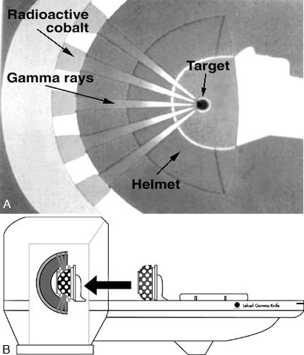
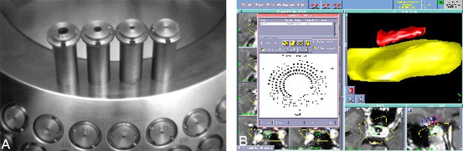
The 201 60 Co sources of the Gamma Knife are almost evenly distributed in five rings constituting part of a hemispherical shell inside the unit (Fig. 4).
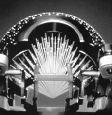
The radiation emitted from each source is directed toward the center of what would be the corresponding whole sphere. This point, where the central axes of all beams intersect (Fig.5), is called the isocenter. The isocenter establishes the principal spatial point of reference for all dose measurements and treatment geometry subsequently used in medical applications of the Gamma Knife. The importance of this spatial coordinate is further emphasized by the fact that the manufacturer’s specifications state that the location of the unit isocenter will always be defined to within ±0.3 mm.
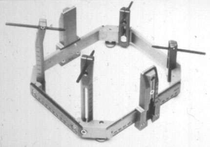
To prevent problems with the unit that might create significant unexpected delays in treatment, the Gamma Knife physicist completes a comprehensive operational and safety check of the unit and verifies the accuracy of its control timer. After the unit and treatment suite have passed this inspection, the attending neurosurgeon affixes the Leksell stereotactic headframe (Fig. 6) to the patient’s skull so that the intended treatment target is located as near as possible to its center. The frame defines the location and orientation of the Leksell Cartesian coordinate system used in target localization and treatment.13 It holds the patient rigidly in position during both imaging and irradiation and permits the attachment of a variety of three-dimensional fiducial marking systems used in conjunction with different imaging modalities such as magnetic resonance (MR) imaging, computed tomography (CT), and angiography.
A series of thin-slice axial images, extending both superiorly and inferiorly to the target(s) of interest, is obtained so that the target can be observed clearly. A second set of the same images, but exhibiting the signal intensity effects of an injected contrast agent, also may be acquired, depending on the patient’s diagnosis. If MR imaging is used, a set of images in the coronal orientation through the anatomy of interest is usually recorded. Typically, the capability to superimpose graphics on these images at the MR/CT control console is taken advantage of to perform crude measurements of the target’s geometry and to obtain the coordinates of the target center in the Leksell frame of reference before imaging has been completed.
During treatment planning, the fiducial markers visible on each of the acquired cross-section/projected images are entered as data points. With this set of information, the treatment-planning computer is able to correlate the position of all image pixels with three-dimensional geometric coordinates in Leksell space. This process of image registration is critical to ensure accurate definition of the treatment geometry.10,11 Consequently, standards for image quality are high. Physicists specializing in diagnostic imaging usually maintain and ensure the optimal performance of MR imaging devices, CT scanners, and angiographic imaging arrays. However, a quick, easily completed series of tests performed during imaging or on the Gamma Knife treatment-planning computer can verify that no image distortion has occurred.
[one_half]
[one_half_last]
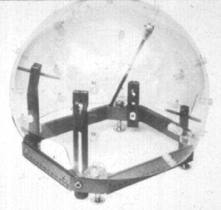
Before treatment planning, the patient will have had his or her skull radii measured with the Gamma Knife skull scaling instrument—a large acrylic sphere with 25 evenly distributed holes for insertion of a measuring rod (Fig. 7). The patient also will have been set in the treatment position on the Gamma Knife unit to determine a comfortable degree of chin and neck flexion, known as the treatment gamma angle . After the measured skull radii have been entered into the treatment planning computer, outlines of the target and critical anatomic structures may be superimposed graphically onto the previously entered cross-sectional/projected image data. The treatment-planning computer is capable of detecting the outlines of internal anatomy using semi-automatic image segmentation, but the user can always manually enter or edit graphically overlayed internal structure boundaries as well. It is good practice to take the time required to outline target and critical structure volumes because these data can later be used to judge exactly how well any designed dose distribution covers the target or misses critical anatomical structures through a process known as dose-volume histogram analysis.
Radiation dose is deposited at the target location by applying one of the “spheres” of dose at a specific desired location. Radiation dose summates according to the Principle of Superposition, and multiple such spheres or shots as referred to by Gamma Knife users may be entered into the treatment plan if sized and spaced appropriately to follow the contours of nonspherically shaped target volumes (all collimator sizes may be combined or used more than once each if desired, Fig. 8). Further refinements in dose shaping are possible by exposing the patient to each shot for different lengths of time (shot weighting) or by using as many as 100 available collimator plugs to block the beams delivered to the target or to immediately adjacent critical structures from any of the unit’s 201 beam channels.
As shots are added, the treatment-planning computer recalculates the radiation-dose distribution in real time. The point receiving the maximum level of radiation dose is always set as the 100% dose point, with dose at all other points defined relative to it. This mathematical redefinition of dose levels, known as normalization, is useful since all doses within the calculation matrix are presented as ratio values. The dose distribution can thus be shaped according to accepted values for the ratio of dose(s) to specific critical surrounding tissue(s) relative to the dose level required for therapeutic effects to be observed within the target tissue.
Sometimes the Leksell frame support bars prevent placement of the patient at desired shot coordinates, but neither the physicist nor the treatment-planning computer can always reliably predict if and when this situation will occur while placing shots during design and calculation of the treatment plan. To address this problem, the extreme x, y, and z values listed among the shot coordinates are noted when the final approved plan is printed. Taking the extra step of checking that these plan coordinates can actually be reached by setting the patient in the treatment position (without delivering any radiation) allows the plan to be adjusted if certain shot locations cannot be achieved physically.
During treatment delivery, the physicist continuously verifies that the collimator helmet(s), Leksell frame coordinates, patient’s position, and plugging patterns specified in the treatment plan are set correctly.1 If plugs are added or deleted from the patterns provided in the plan, the physicist adjusts the duration of the shot accordingly. Changes in the plug pattern may be necessary since the attending physician usually checks beam channels that could potentially direct radiation to the lenses of the eyes. Because a patient’s eyes may move during treatment and their lenses thus are not fixed at the locations defined for them (as taken from the cross-sectional images entered into the treatment planning system earlier), extra precautions for shielding the eyes may be necessary.
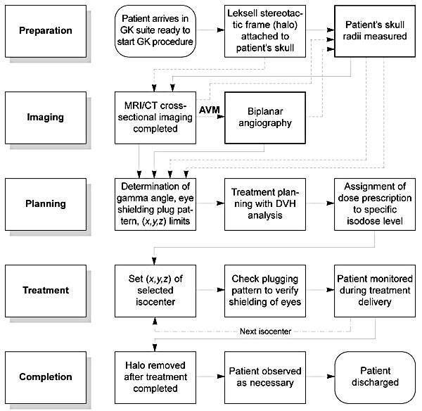
When the treatment is complete, documentation noting the actual treatment administered is signed by the attending neurosurgeon, radiation oncologist, and physicist. The Gamma Knife unit is shut down to prevent its unauthorized use, and the patient’s computer-treatment planning information is backed up and archived for future reference. A flow chart condensing all of the treatment planning and delivery steps described above is presented in Figure 9.
Conclusion
Although not a widely known profession, Medical Physics plays a crucial role in many technologically intensive medical disciplines, including (but not necessarily limited to) cardiology, diagnostic and interventional radiology, neurology, neurosurgery, nuclear medicine, ophthalmology, pathology, and radiation oncology. In particular, the contributions and responsibilities of medical physicists in supporting the safe, accurate, and reliable delivery of cyclotron, Gamma Knife, or linear accelerator-based stereotactic radiosurgery make them an integral part of any interdisciplinary team involved in this practice.7
Acknowledgment
The author thanks Ann H. Maitz, MSc, Medical Physicist at the University of Pittsburgh Center for Image-Guided Neurosurgery, for generously granting permission to reproduce data collected on her institution’s recently installed Model B Gamma Knife in this publication.
†One Gy (gray) is defined as one joule of energy absorbed per kilogram mass of energy-absorbing medium (i.e., tissue), where one joule is the energy required to accelerate a 1-kg mass at a rate of 1 m/sec2 for a distance of 1m.
References
- Flickinger JC, Lunsford LD, Kondziolka D, et al: Potential human error in setting stereotactic coordinates for radiosurgery: Implications for quality assurance. Int J Radiat Oncol Biol Phys 27:397-401, 1993
- Goetsch SJ: Stereotactic radiosurgery using the Gamma Knife, in Palta J, Mackie TR (eds): Teletherapy: Present and Future. Madison, WI: Advanced Medical Publishing, 1996, pp 611-642
- Heydarian M, Hoban PW, Beddoe AH: A comparison of dosimetry techniques in stereotactic radiosurgery. Phys Med Biol 41:93-110, 1996
- Higgins PD, Sibata CH, Siskind L, et al: Deconvolution of detector size effect for small field measurement. Med Phys 22:1663-1666, 1995
- Johns HE, Cunningham JR: The Physics of Radiology. Springfield, IL: Charles C Thomas, 1983, pp 557-669
- Kondziolka D, Lunsford LD, Flickinger JC: Current concepts in Gamma Knife radiosurgery. Neurosurg Quarterly 3:253-271, 1993
- Larson DA, Bova F, Eisert D, et al: Current radiosurgery practice: Results of an ASTRO survey. Task Force on Stereotactic Radiosurgery, American Society for Therapeutic Radiology and Oncology. Int J Radiat Oncol Biol Phys 28:523-526, 1994
- Leksell L: The stereotaxic method and radiosurgery of the brain. Acta Chir Scand 102:316-319, 1951
- Maitz AH, Wu A, Lunsford LD, et al: Quality assurance for gamma knife stereotactic radiosurgery. Int J Radiat Oncol Biol Phys 32:1465-1471, 1995
- McKenzie MR, Souhami L, Podgorsak EB, et al: Photon radiosurgery: A clinical review. Can J Neurol Sci 19:212-221, 1992
- Podgorsak EB, Pike GB, Pla M, et al: Radiosurgery with photon beams: Physical aspects and adequacy of linear accelerators.Radiother Oncol 17:349-358, 1990
- Task Group 21, Radiation Therapy Committee, American Association of Physicists in Medicine: A protocol for the determination of absorbed dose from high-energy photon and electron beams. Med Phys 10:741-771, 1983
- Wu A, Lindner G, Maitz AH, et al: Physics of gamma knife approach on convergent beams in stereotactic radiosurgery. Int J Radiat Oncol Biol Phys 18:941-949, 1990